Custom pipe spool fabrication under ASME B31.3 and ASME Section IX certification reduces field welding labor by 40–60%, cuts overall piping installation time by 30–50%, and lowers construction site incident rates by up to 35% compared to stick-built field piping — making prefabricated pipe spools the most measurable risk-reduction strategy available to project engineers and EPC contractors today. At MWalloys, we have manufactured and delivered ASME-certified pipe spool packages for refineries, chemical plants, LNG terminals, and pharmaceutical facilities across three continents, and every project confirms the same pattern: the earlier prefabrication planning begins, the greater the schedule compression and cost savings achieved on site.
If your project requires the use of Custom Pipe Spools Fabrication, you can contact us for a free quote.
What Is a Pipe Spool and How Does Custom Fabrication Differ From Field Construction?
A pipe spool is a prefabricated section of a piping system that includes pipe segments, fittings, flanges, elbows, tees, reducers, and branch connections assembled and welded in a controlled shop environment before delivery to the construction site. The term "spool" originates from the reel-like appearance of a flanged pipe assembly and is now universally used across the oil and gas, petrochemical, power generation, and industrial construction industries.
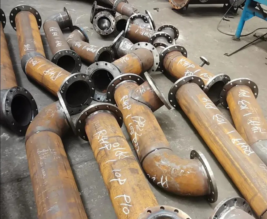
Custom pipe spool fabrication means each spool is manufactured to project-specific isometric drawings, material specifications, pressure ratings, and dimensional requirements — as opposed to purchasing catalogue-standard pipe assemblies that require site modification.
Pipe Spool vs. Field-Fabricated Piping: A Direct Comparison
The core difference between prefabricated spools and conventional field piping construction comes down to where the value is added and where the risk is concentrated.
| Parameter | Prefabricated Pipe Spools | Field-Fabricated Piping |
|---|---|---|
| Welding Environment | Controlled shop: stable temperature, humidity, positioning | Variable: wind, rain, confined spaces, awkward positions |
| Welder Productivity | 3–5 joints per shift (shop) | 1–2 joints per shift (field) |
| NDE Access | Full 360° access, optimal equipment positioning | Restricted access in many field conditions |
| Rework Rate | 2–5% (industry average, shop environment) | 8–15% (field environment) |
| Material Traceability | Centralized heat number documentation | Distributed, harder to maintain |
| Safety Incident Rate | Lower — controlled environment, no height work for most joints | Higher — elevated work, confined spaces, concurrent trades |
| Schedule Predictability | High — shop production is weather-independent | Lower — weather delays, workforce scheduling conflicts |
| Quality Documentation | Comprehensive data packages per spool | Often fragmented across field records |
Source: Construction Industry Institute (CII) Research Report 171-11, "Modularization: How to Optimize? How to Maximize Its Value?"; Dodge Data & Analytics, "Prefabrication and Modularization in Construction" (2020 SmartMarket Report).
What Components Are Included in a Custom Pipe Spool Package?
A complete custom pipe spool typically consists of:
- Pipe segments: Cut to precise lengths from ASTM-certified pipe stock.
- Welding neck flanges or slip-on flanges: Pressure class rated per ASME B16.5 or B16.47.
- Butt-welding fittings: Elbows (long radius or short radius), tees, reducers, caps per ASME B16.9.
- Socket weld fittings: For smaller bore piping (typically 2 inches NPS and below) per ASME B16.11.
- Branch connections: Weldolets, sockolets, threadolets per MSS SP-97.
- Structural attachments: Pipe shoes, dummy supports, trunnions as specified on isometrics.
- In-line instruments: Thermowell nozzles, pressure tap connections, orifice flanges as required.
At MWalloys, we treat each spool as a complete deliverable with its own data package: material test reports, weld maps, NDE results, dimensional inspection records, and hydrostatic or pneumatic test certification.
Which ASME Standards Govern Pipe Spool Fabrication and Certification?
ASME (American Society of Mechanical Engineers) certification is not a single document — it is a layered framework of codes that address different aspects of pipe spool design, fabrication, testing, and documentation. Understanding which standards apply to your project is essential before issuing a fabrication inquiry.
The Core ASME Code Framework for Pipe Spool Fabrication
| ASME Standard | Scope | Key Requirements |
|---|---|---|
| ASME B31.3 | Process Piping (chemical, petroleum, pharmaceutical) | Design pressure/temperature, material specs, welding, examination, testing |
| ASME B31.1 | Power Piping (steam, feedwater, turbine systems) | Higher examination requirements than B31.3 for equivalent pressures |
| ASME B31.4 | Pipeline Transportation Systems for Liquids | Onshore liquid pipeline fabrication |
| ASME B31.8 | Gas Transmission and Distribution Pipelines | Gas service design and fabrication |
| ASME Section II | Materials Specifications | Approved material specifications (Part A: ferrous; Part B: nonferrous; Part C: welding consumables) |
| ASME Section IX | Welding and Brazing Qualifications | WPS, PQR, WPQ requirements — mandatory for all pressure-containing welds |
| ASME B16.5 | Pipe Flanges and Flanged Fittings (NPS ½ through NPS 24) | Pressure class ratings, dimensions, materials. |
| ASME B16.9 | Factory-Made Wrought Buttwelding Fittings | Dimensional and tolerance standards for fittings |
| ASME B16.11 | Forged Fittings, Socket-Welding and Threaded | Small bore fitting standards |
| ASME B16.25 | Buttwelding Ends | Weld end preparation dimensions |
Source: ASME Standards Collection, 2023 edition; ASME B31.3-2022 Process Piping Code.
What Does ASME Certification Mean for a Pipe Spool Fabricator?
The term "ASME certified" when applied to a pipe spool fabricator typically refers to one or more of the following authorizations:
ASME "U" Stamp: Authorizes manufacture of pressure vessels under ASME Section VIII Division 1. While not directly a pipe spool stamp, U-stamp shops demonstrate comprehensive pressure equipment manufacturing capability.
ASME "S" Stamp: Authorizes power boiler fabrication under Section I. Relevant for B31.1 power piping spool fabrication.
National Board "NB" registration: Products manufactured and registered with the National Board of Boiler and Pressure Vessel Inspectors, providing third-party verification of code compliance.
More relevant to most pipe spool work: Many projects do not require an ASME stamp on the spools themselves but do require strict code compliance. ASME B31.3 Section 300.2 makes the Owner responsible for designating the applicable code edition and establishing the inspection requirements. The practical implication: a fabricator must demonstrate:
- An approved Quality Management System (QMS) consistent with ASME Section IX requirements.
- Qualified Welding Procedure Specifications (WPS) and Procedure Qualification Records (PQR) covering all material groups, positions, and processes to be used.
- Welder Performance Qualifications (WPQ) current for all welders who will work on the project.
- A designated Authorized Inspector (AI) or Owner's Inspector for code compliance verification.
At MWalloys, our QMS is structured to comply with ASME B31.3, B31.1, and Section IX requirements, with third-party inspectors available for client-witnessed qualification testing and hold-point inspections.
Fluid Service Categories Under ASME B31.3 and Their Impact on Fabrication Requirements
ASME B31.3 categorizes fluid services into distinct classes that drive examination requirements and consequently affect fabrication cost and schedule:
| Service Category | Definition | Examination Requirement | Impact on Spool Cost |
|---|---|---|---|
| Normal Fluid Service | Standard process fluids within defined pressure/temperature | 5% random radiographic or ultrasonic examination of welds | Baseline |
| Category D | Low pressure (≤ 150 psig), non-flammable, non-toxic, ≥ -20°F | Visual examination only | -15 to -25% vs. Normal |
| Category M | Toxic fluids — single exposure could be lethal | 100% radiographic or ultrasonic examination | +40 to +60% vs. Normal |
| High Pressure | Systems designed above ASME B16.5 Class 2500 | 100% examination, additional requirements | +60 to +100% vs. Normal |
| Elevated Temperature | Cr-Mo alloys in creep range service | Specific PWHT and examination requirements | +30 to +50% vs. Normal |
Source: ASME B31.3-2022, Chapter VI — Inspection, Examination, and Testing.
Understanding your project's fluid service category at the outset determines examination scope, which directly affects fabricator selection, schedule, and budget.
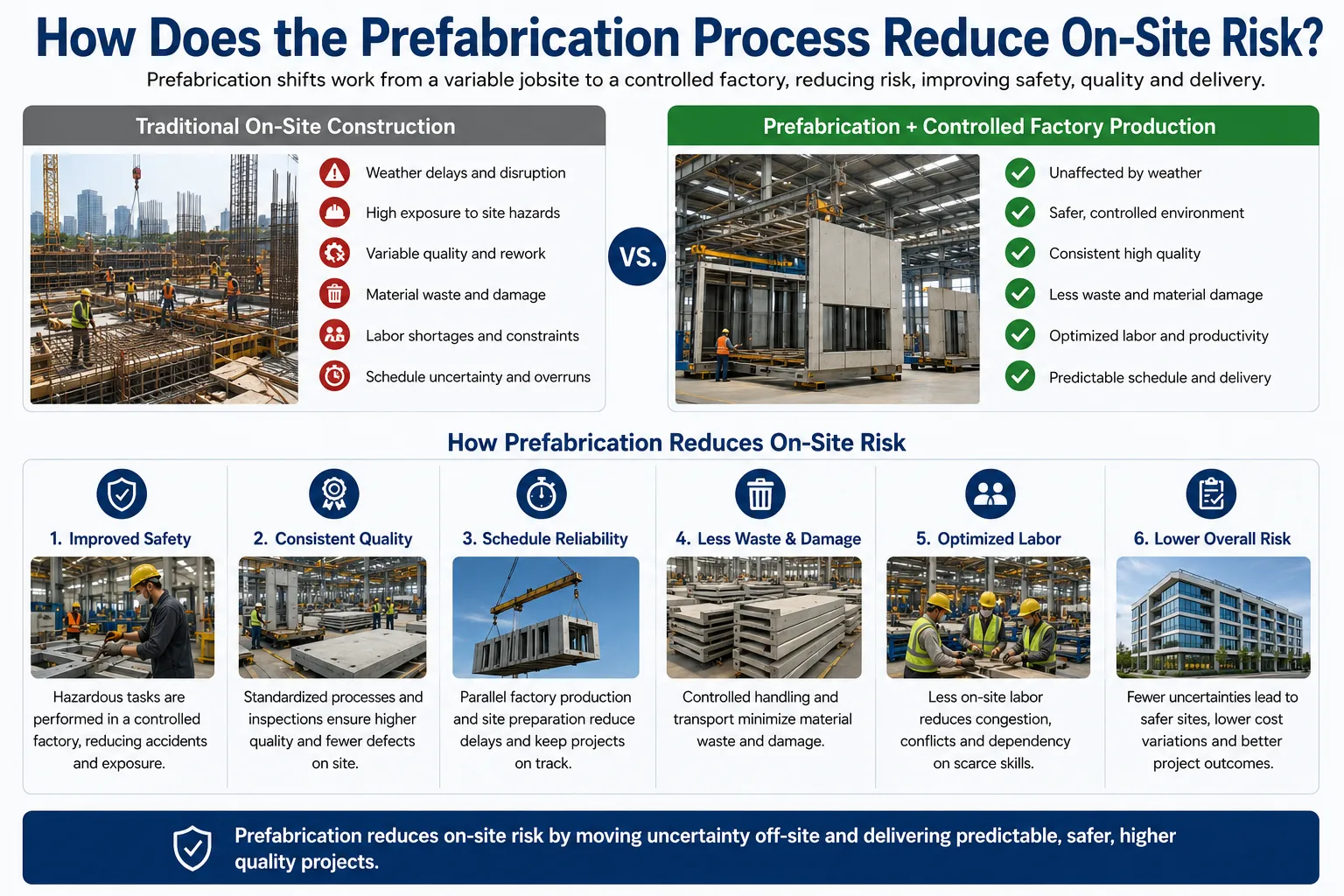
How Does the Prefabrication Process Reduce On-Site Risk?
This is the central value proposition of custom pipe spool fabrication, and the data supporting it is substantial. Risk reduction operates across four dimensions: safety, quality, schedule, and cost.
Safety Risk Reduction Through Shop Fabrication
Construction sites rank among the highest-risk work environments across all industries. According to the U.S. Bureau of Labor Statistics (BLS), the construction industry recorded an injury rate of 3.3 cases per 100 full-time workers in 2022 — compared to manufacturing environments (pipe fabrication shops) at 2.8 cases per 100 full-time workers. The differential is modest in absolute terms, but the nature and severity of incidents differs significantly.
Field pipe welding typically requires:
- Elevated work platforms (scaffolding, aerial lifts) for pipe runs above grade.
- Confined space entry for welding in vessels, columns, and underground structures.
- Hot work permits with concurrent fire watch requirements.
- Coordination with simultaneous construction trades in congested areas.
Shop fabrication eliminates most of these risk categories. At MWalloys, our shop-based welding produces joints in the flat (1G), horizontal (2G), and overhead positions using rotating pipe positioners — not scaffold-mounted welders in awkward positions. This positional advantage alone improves both safety and weld quality simultaneously.
The Construction Industry Institute (CII) Report RT-283, "Improving Productivity Through Prefabrication" (2014), found that projects with high prefabrication content had 25–35% fewer recordable safety incidents compared to equivalent field-constructed projects.
Quality Risk Reduction: Why Shop Welding Outperforms Field Welding
The controlled shop environment produces measurably superior weld quality across multiple metrics:
Temperature and humidity control: ASME B31.3 requires that welding not be performed when ambient temperature is below -20°F, or when surfaces are wet, or in high winds without adequate protection. Shop environments maintain these conditions consistently without project team intervention.
Joint fit-up quality: Shop fabrication uses precision pipe cutting saws, CNC pipe beveling machines, and fit-up fixtures that achieve consistent gap dimensions (typically 1/16 inch ± 1/32 inch per ASME B16.25). Field fit-up on partially erected systems, where thermal expansion has already altered dimensions, is consistently less precise.
Preheat control: For alloy materials requiring preheat (carbon steel above 1 inch wall thickness, chrome-moly alloys per ASME Section IX Table QW-406), shop heating with induction coils or electric resistance blankets maintains uniform preheat temperature across the joint perimeter. Field propane or oxy-acetylene preheating is less uniform and harder to verify.
Interpass temperature control: Critical for creep-strength enhanced ferritic (CSEF) steels like P91, where interpass temperature limits (typically 400°F maximum) are essential for microstructural integrity. Shop digital pyrometers at every weld station provide continuous monitoring.
A 2019 study published in the Journal of Construction Engineering and Management (ASCE, Volume 145, Issue 3) found that prefabricated pipe spools had a radiographic rejection rate of 2.1% compared to 7.8% for equivalent field welds in a matched comparison of refinery piping installations.
Schedule Risk Reduction: Parallel Path Execution
One of the most powerful but underappreciated benefits of pipe spool prefabrication is the ability to execute fabrication in parallel with site civil and structural work. This schedule compression capability fundamentally changes project critical path analysis.
In a traditional sequential construction approach:
- Civil foundations complete → Structural steel erection → Pipe rack erection → Field pipe installation → Tie-in and testing
In a prefabrication-integrated approach:
- Civil foundations AND pipe spool fabrication run simultaneously.
- Structural steel AND pipe spool delivery preparation run simultaneously.
- Pipe installation begins immediately after rack erection using pre-fabricated spools.
- Testing begins sooner because field joint count is dramatically reduced.
According to McKinsey & Company's 2016 report "Imagining Construction's Digital Future," projects that implement prefabrication and modularization strategies achieve schedule reductions of 20–40% on the piping installation phase. For a large refinery with 80,000 to 150,000 pipe spool welds, this represents months of schedule compression on the critical path.
At MWalloys, we work with project planners during the front-end engineering phase (FEED) to develop spool release schedules synchronized with field installation sequences. This requires early isometric drawing availability, which creates a virtuous cycle: projects that commit to prefabrication earlier produce better engineering faster.
Cost Risk Reduction: Where the Savings Actually Come From
The cost advantage of prefabricated pipe spools is real but requires nuanced analysis. Fabrication shop labor costs are not inherently lower than field labor rates in all markets. The cost savings derive from:
Productivity differential: Shop welders consistently achieve 3–5 completed joints per shift; field welders average 1.5–2.5 joints per shift in most industrial construction environments. This 2–3× productivity differential is the primary cost driver. Source: NECA Manual of Labor Units; MCAA (Mechanical Contractors Association of America) labor productivity data.
Rework cost elimination: A single field weld repair requires: radiographic re-examination, weld removal (grinding or gouging), pre-heat reinstatement, re-welding, post-weld heat treatment if applicable, NDE re-examination, documentation update. Total cost of a single field weld repair can range from USD 2,000 to USD 15,000 depending on pipe size, alloy, and access difficulty. Reducing field weld count by 60% directly reduces repair cost exposure.
Overhead rate differences: Construction site overhead (scaffolding, temporary facilities, safety personnel, concurrent trade coordination) adds 15–40% to direct labor costs. Shop overhead, while real, is typically lower as a percentage of direct labor.
Turnover and availability: Specialized field welders command premium mobilization packages and are subject to market availability constraints. Shop fabricators maintain permanent, qualified workforces.
The combined effect: CII research (Report 171-11) documents an average total installed cost reduction of 15–25% for projects that achieve 50% or greater prefabrication content in their piping scope.
What Materials Are Used in Custom Pipe Spool Fabrication?
Material selection for pipe spools is driven by the fluid service (chemistry, temperature, pressure), regulatory requirements, and project economics. ASME Section II and B31.3 provide the approved material specifications.
Common Pipe Spool Materials by Service Type
| Material | ASTM Specification (Pipe) | Temperature Range | Typical Application |
|---|---|---|---|
| Carbon Steel (A106 Gr. B) | ASTM A106/A53 | -20°F to 800°F (-29°C to 427°C) | General process, utility, steam |
| Low-Temp Carbon Steel (A333 Gr. 6) | ASTM A333 | -50°F to 400°F (-46°C to 204°C) | LNG, cryogenic process |
| 316/316L Stainless Steel | ASTM A312 | -325°F to 800°F (-198°C to 427°C) | Corrosive process, pharmaceutical |
| 304/304L Stainless Steel | ASTM A312 | -325°F to 800°F | General corrosion resistance |
| Duplex 2205 (UNS S31803) | ASTM A790 | -50°F to 600°F (-46°C to 315°C) | Chloride-containing service |
| 1.25Cr-0.5Mo (P11) | ASTM A335 | to 1,050°F (565°C) | High-temp, steam service |
| 2.25Cr-1Mo (P22) | ASTM A335 | to 1,100°F (593°C) | Hydrogen service, high-temp |
| 9Cr-1Mo-V (P91) | ASTM A335 | to 1,200°F (649°C) | Ultra-supercritical steam |
| Inconel 625 (UNS N06625) | ASTM B444 | Cryogenic to 1,800°F (982°C) | Highly corrosive, high-temp |
| Titanium Grade 2 | ASTM B337 | Cryogenic to 300°F (149°C) | Seawater, halide service |
| HDPE-lined Carbon Steel | ASTM A106 + ASTM F1545 liner | 32°F to 180°F (0°C to 82°C) | Acid service, slurry piping |
Source: ASME B31.3-2022 Appendix A — Allowable Stresses; ASTM International material specifications.
Material Certification Requirements for ASME Pipe Spools
Every piece of material incorporated into an ASME-compliant pipe spool must be traceable to a certified mill test report (MTR) that documents:
- Chemical composition (heat analysis and product analysis results).
- Mechanical properties (tensile strength, yield strength, elongation, Charpy impact results where required).
- Heat treatment condition.
- Heat number and lot number.
- Manufacturer's name and facility.
- ASTM/ASME specification and grade conformance statement.
At MWalloys, we maintain a material receiving inspection procedure that physically verifies each incoming material piece against its MTR before any cutting, fitting, or welding begins. Heat numbers are transferred to sub-pieces after cutting and documented on the weld map for each spool. This traceability chain is a non-negotiable requirement for ASME code compliance and client inspection verification.
Special Considerations for Chrome-Moly (Cr-Mo) Pipe Spool Fabrication
Chrome-moly alloys (P11, P22, P91) deserve specific attention because they present fabrication challenges that standard carbon steel procedures cannot address. These materials are used in high-temperature power and process piping where creep strength at elevated temperatures is the primary design driver.
P91 (9Cr-1Mo-V) is particularly demanding:
- Minimum preheat: 400°F (204°C) per ASME B31.1 and most client specifications.
- Interpass temperature maximum: 400°F (204°C) — the preheat minimum and interpass maximum are nearly identical, requiring continuous thermal management.
- Post-Weld Heat Treatment (PWHT): Required at 1,375–1,400°F (746–760°C) per ASME Code Case 2328-1, with controlled heating and cooling rates.
- Hardness verification: Post-PWHT hardness must be within 190–275 HBW (Brinell Hardness) to confirm proper microstructure.
- Delta ferrite risk: Incorrect PWHT can result in delta ferrite formation, which dramatically reduces creep life. Surface replica metallography at hold-point inspections is recommended for critical P91 welds.
We do not subcontract P91 PWHT to third-party services without direct oversight. Temperature uniformity across the weld joint during PWHT must be maintained within ±25°F, which requires properly calibrated induction PWHT systems with multi-point thermocouple monitoring.
How Are Pipe Spools Designed, Modeled, and Dimensionally Controlled?
The accuracy of a custom pipe spool is only as good as the design input and dimensional control processes that produce it. Errors in isometric drawings, material takeoffs, or shop measurement translate directly into costly field fit-up problems.
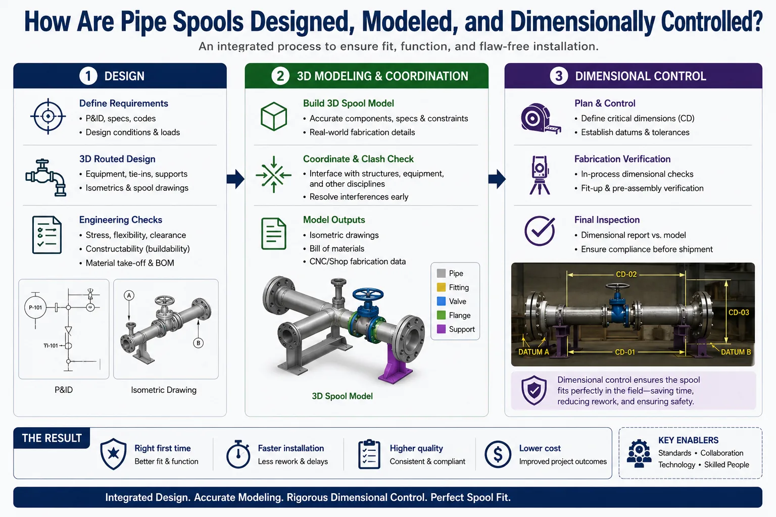
From P&ID to Isometric Drawing to Shop Fabrication
The engineering-to-fabrication workflow follows this sequence:
- P&ID (Piping and Instrumentation Diagram): Defines process requirements, instrument locations, valve types, and connection points. This is the functional specification from which piping design derives.
- 3D Plant Model: Using software platforms such as AVEVA E3D, PDMS, Intergraph Smart 3D, or Bentley OpenPlant, the piping designer routes pipe through the 3D model while respecting structural interferences, maintenance clearances, and support locations. The 3D model serves as the single-source geometric truth for the project.
- Isometric Drawing (ISO) Extraction: Automated isometric drawings are extracted from the 3D model for each spool. The ISO shows: spool tag number, pipe routing geometry with dimensions, material specifications, weld identification numbers, bill of materials (BOM) for all components, NDE requirements, PWHT requirements, pressure testing requirements, and weight/center of gravity data.
- Material Take-Off and Procurement: The ISO BOM drives material requisitions for pipe, fittings, flanges, and specialty items. Material lead times (especially for alloy materials) must be factored into the fabrication schedule.
- Shop Fabrication Drawing (if required): For complex assemblies or where contractor shop drawing practice differs from client ISO format, shop drawings may be prepared from the ISO before fabrication begins.
Dimensional Tolerance Standards for Pipe Spools
Dimensional accuracy of fabricated pipe spools determines field fit-up success. Tight tolerances in the shop prevent costly field cutting, rewelding, or spool replacement.
| Dimension | Typical Tolerance | Basis |
|---|---|---|
| Overall spool length (end-to-end flange face) | ±3 mm (±1/8 inch) | Common industry practice; client specifications vary |
| Flange face orientation (rotational) | ±1° | Client spec; critical for bolt hole orientation |
| Flange bolt hole straddle from centerline | ±1 mm (±1/16 inch) | ASME B16.5 |
| Pipe cut length | ±1.5 mm (±1/16 inch) | Common shop practice |
| Bend angle (for pipe bends, not fittings) | ±0.5° | ASME B16.49 |
| Out-of-plane dimensions (elevation difference) | ±3 mm (±1/8 inch) | Project-specific |
| Flange squareness (perpendicularity to pipe axis) | ≤ 0.5 mm TIR (0.020 inch) | Client spec |
Source: MSS SP-69 Pipe Hangers and Supports; common industrial spool fabrication specifications from major EPC contractors (Bechtel, Fluor, Wood Group standard pipe spool specifications).
3D Scanning and Digital Measurement in Modern Spool Fabrication
Leading pipe spool fabricators now integrate laser scanning and digital measurement into final inspection workflows. At MWalloys, we use portable coordinate measuring arm (PCMA) technology for spools where critical dimensional interfaces require verification beyond manual tape measurement.
Benefits of digital measurement in spool inspection:
- Flange face position and orientation verified to ±0.5 mm in 3D space.
- Overall geometry compared directly to 3D model reference coordinates.
- Measurement data becomes part of the digital as-built record.
- Detected discrepancies can be corrected in the shop at fraction of field correction cost.
For mega-projects (above 50,000 spool welds), some EPC contractors have implemented full photogrammetric measurement of all completed spools, creating a digital as-built database that enables real-time field installation planning and interference detection.
What Welding Procedures and Qualification Requirements Apply to ASME Pipe Spools?
Welding is the most safety-critical and quality-critical activity in pipe spool fabrication. ASME Section IX establishes the qualification framework that all ASME-compliant fabrication must follow.
The WPS/PQR/WPQ Qualification Triad
Welding Procedure Specification (WPS): A document that specifies the welding variables (base metal P-Number group, filler metal F-Number, process, position, joint design, preheat, interpass temperature, PWHT, current, voltage, travel speed, etc.) that must be followed during production welding. A fabricator must have a qualified WPS for every combination of variables present in the project scope.
Procedure Qualification Record (PQR): The test record that documents the welding of a test coupon using variables that support the WPS, along with the destructive test results (tensile, bend, impact, hardness as required) that verify the procedure produces welds meeting the acceptance criteria of ASME Section IX.
Welder Performance Qualification (WPQ): An individual welder's demonstration of ability to produce acceptable welds using a specific process, position, and base metal combination. Welder qualifications must be maintained through continued work or periodic re-testing per ASME Section IX QW-322.
Common Welding Processes in Pipe Spool Fabrication
| Welding Process | ASME Section IX Designation | Typical Application | Advantages |
|---|---|---|---|
| GTAW (TIG) | Process 141 | Root pass, thin wall, alloy materials | Highest weld quality, no slag |
| SMAW (Stick) | Process 111 | Fill and cap passes, carbon steel | Versatile, low equipment cost |
| GMAW (MIG) | Process 135 | Carbon steel fill passes, production welding | High deposition rate |
| FCAW (Flux Core) | Process 136/137 | Carbon steel production welding | High productivity, all-position |
| SAW (Submerged Arc) | Process 121 | Large diameter, heavy wall, straight seams | Very high deposition rate |
| GTAW + SMAW (Combined) | 141 + 111 | Alloy and stainless piping | TIG root quality + SMAW fill productivity |
| Orbital GTAW | Process 141 (automated) | Small bore stainless, pharmaceutical, semiconductor | Consistent automated quality |
Post-Weld Heat Treatment Requirements by Material
| Material Group (ASME P-Number) | PWHT Required? | Temperature Range | Holding Time per Inch of Thickness |
|---|---|---|---|
| P1 (Carbon Steel) | Required above 3/4 inch (19 mm) wall per B31.3 | 1,100–1,200°F (593–649°C) | 1 hour minimum |
| P4 (1-1/4Cr-1/2Mo) | Required above 1/2 inch (13 mm) wall | 1,300–1,375°F (704–746°C) | 1 hour minimum |
| P5A (2-1/4Cr-1Mo, P22) | Required above 1/2 inch | 1,300–1,375°F (704–746°C) | 1 hour minimum |
| P5B (9Cr-1Mo-V, P91) | Always required | 1,375–1,400°F (746–760°C) | 1 hour minimum per inch, 2 hours minimum |
| P8 (Austenitic Stainless) | Generally not required (solution annealing if sensitization risk) | N/A or 1,900–2,100°F | Project-specific |
| P15E (Duplex Stainless) | Solution anneal may be required after heavy fabrication | 1,900–2,050°F (1038–1121°C) | Rapid quench required |
Source: ASME B31.3-2022 Table 331.1.1 — Requirements for PWHT; ASME B31.1-2022.
What Non-Destructive Examination Methods Are Required for Certified Pipe Spools?
NDE (Non-Destructive Examination) is the quality verification step that confirms weld integrity without destroying the completed spool. The required methods, scope, and acceptance criteria are specified in the applicable code (B31.3, B31.1) and project specification.
NDE Method Comparison for Pipe Spool Welds
| NDE Method | Detects | Sensitivity | Limitations | Cost Index |
|---|---|---|---|---|
| Visual Examination (VT) | Surface defects, dimensional verification | Low (surface only) | Cannot detect subsurface defects | 1× (baseline) |
| Radiographic Testing (RT) | Volumetric — porosity, inclusions, cracks, lack of fusion | High | Radiation safety, limited on thick wall | 5–8× |
| Ultrasonic Testing (UT) — Conventional | Planar defects, laminations, thickness | High | Operator-dependent, surface prep needed | 4–7× |
| Phased Array Ultrasonic Testing (PAUT) | Volumetric and planar — superior to conventional UT | Very High | Higher equipment cost | 7–12× |
| Magnetic Particle Testing (MT) | Surface and near-surface defects in ferromagnetic materials | Medium-High | Ferromagnetic materials only | 2–3× |
| Liquid Penetrant Testing (PT) | Surface-open defects in any material | Medium | Surface only; no subsurface detection | 1.5–2× |
| Positive Material Identification (PMI) | Elemental chemistry verification | High | Not an NDE method per se, but quality verification | 1.5× |
Source: ASME Section V — Non-Destructive Examination; API 570 Piping Inspection Code; ASNT (American Society for Nondestructive Testing) Level III study guides.
NDE Requirements Under ASME B31.3 by Service Category
Normal Fluid Service: 5% random examination of welds. This means that in a batch of 100 welds, 5 welds are selected for full RT or UT examination. If a defective weld is found in the 5% sample, two additional welds from the same welder must be examined for each defect found. This escalation process continues until either a passing examination result is obtained or 100% examination is invoked for that welder's work.
The statistical logic of the 5% random examination requirement means that a single rejection triggers examination of 6–10 additional welds, making the true examination scope sensitive to weld quality. A fabricator with a 2% repair rate performs very differently under this system than one with a 10% repair rate.
Category M Service: 100% examination of all pressure-containing welds using RT or UT. This requirement typically doubles the NDE cost component of a spool fabrication project compared to Normal service.
Hydrostatic and Pneumatic Pressure Testing Requirements
Beyond NDE, ASME B31.3 requires pressure testing of completed piping systems. For pipe spools tested in the shop (a practice we recommend where possible), the test parameters are:
Hydrostatic test: Test pressure = 1.5 × design pressure × (allowable stress at test temperature / allowable stress at design temperature). Minimum hold time: 10 minutes per ASME B31.3 Para. 345.4.2. Water is the standard test medium; temperature must be above the brittle fracture transition temperature of the material.
Pneumatic test (where hydrostatic is impractical): Test pressure = 1.1 × design pressure. Pneumatic testing stores significantly more energy than hydrostatic testing and presents greater safety risk. ASME B31.3 requires a preliminary leak check at 25% of test pressure before proceeding to full test pressure.
Shop-tested spools reduce field testing scope and duration, since only the field tie-in welds (a small fraction of total weld count) require field testing.
How Does Pipe Spool Logistics and Sequencing Improve Field Installation Efficiency?
Fabricating pipe spools correctly is only half the equation. Delivering them to site in the right sequence, at the right time, with the right documentation, determines whether the investment in prefabrication translates to measurable field productivity gains.
Spool Identification and Tracking Systems
Every fabricated spool must be uniquely identified and trackable from shop to installation. Industry-standard identification includes:
- Spool tag number: Matching the ISO drawing tag number (typically formatted as Unit-Line Number-Spool Number, e.g., 100-3"-P-001-CS-001).
- Color coding by material: Red for carbon steel, blue for stainless steel, yellow for chrome-moly (client specifications vary but color coding dramatically reduces field misidentification incidents).
- RFID or barcode tags: For large projects, electronic tracking enables real-time status visibility — fabrication complete, NDE complete, PWHT complete, dimensional inspection complete, released for shipment, arrived on site, installed.
At MWalloys, we maintain a spool tracking database updated at each fabrication milestone. Clients with project management portals receive daily status updates, enabling field construction planners to adjust installation sequences based on actual spool delivery status rather than planned delivery dates.
Transportation and Preservation Requirements
Completed pipe spools require specific protection during transportation:
Flange face protection: Bolted-on plastic or wooden flange protectors prevent damage to raised faces (RF) or ring-type joint (RTJ) grooves that are critical sealing surfaces.
End caps: Plastic push-in end caps or taped covers for open pipe ends prevent contamination entry.
Stainless steel protection: Separation from carbon steel transport components to prevent iron contamination; stainless spools wrapped or crated separately.
Cleanliness requirements: Process piping for pharmaceutical, food, or semiconductor service may require nitrogen purging and sealed end closure immediately after final cleaning and before transport.
Dimensional protection for thin-wall spools: Temporary internal support braces for large-diameter thin-wall spools that could deform under transport loads.
Documentation package delivery: Each spool shipment should be accompanied by or preceded by its complete data package: ITP (Inspection and Test Plan) completion records, weld maps, NDE reports, PWHT charts, dimensional inspection records, and material certifications.
Site Sequencing Strategy to Minimize Field Crane Utilization
One frequently overlooked efficiency benefit of prefabricated spools is the ability to plan crane lifts more precisely. Field pipe installation is often paced by crane availability, which is a shared resource across multiple construction areas.
Delivering spools in the exact installation sequence — matching the bottom-up, section-by-section erection of pipe racks — eliminates the need for temporary laydown and re-handling on site. This "just-in-time" delivery philosophy requires:
- Close coordination between the fabrication shop release schedule and the field installation crew's working sequence.
- Minimum 2-week look-ahead delivery planning.
- Clearly defined site laydown areas with capacitated planning (weight and footprint per spool).
- Expediting protocols for spools on the critical path that are running behind fabrication schedule.
According to a Fluor Corporation internal benchmarking study (referenced in the CII Annual Conference proceedings, 2018), projects with sequenced spool delivery programs achieved 28% higher pipe installation productivity (measured in joint-inches of welding per crew-day) compared to projects with bulk delivery and site-sorting approaches.
How Do You Evaluate and Select a Qualified Pipe Spool Fabricator?
Selecting the right fabrication partner for a critical piping scope is a decision with significant consequences. The cheapest bid is rarely the most economical outcome once field correction costs, schedule delays, and quality failures are factored in.
Fabricator Qualification Evaluation Criteria
| Evaluation Category | What to Assess | How to Verify |
|---|---|---|
| Code Compliance History | Active WPS/PQR library, current WPQ records, experience with applicable codes | Document review, reference projects |
| Welder Qualification | Current WPQs for all required processes and positions, re-test history | Review WPQ logs, witness sample test if needed |
| NDE Capabilities | In-house vs. subcontracted NDE, ASNT Level II/III personnel certificates | Review NDE personnel certification records |
| Material Control | Receiving inspection procedure, heat number traceability, quarantine system | Audit incoming material storage and records |
| PWHT Capability | In-house furnaces or induction equipment, calibration records, thermocouple calibration | Equipment inspection, calibration records |
| Quality Management System | Written QMS document, internal audit history, NCR (Non-Conformance Report) history | Document review, site audit |
| Dimensional Control | Measuring equipment list and calibration records, dimensional inspection procedures | Equipment inspection, sample inspection records |
| Production Capacity | Total shop area, welding bays, active workforce, current backlog | Shop visit, production schedule review |
| Reference Projects | Completed projects of comparable scope, material, and code | Owner-verified reference contacts |
Red Flags in Pipe Spool Fabrication Bidding
Certain patterns in a fabrication proposal indicate risk that may not be obvious from the bid price alone:
Abnormally low price without scope clarification: May indicate misunderstood examination scope (quoting 5% RT instead of 100% RT for Category M service).
WPS/PQR gaps: If the bidder cannot provide existing qualified procedures for your specific material groups and welding positions, procedure qualification adds 4–8 weeks and USD 15,000–50,000 in additional cost before production can begin.
Subcontracted NDE without defined oversight: NDE subcontractors not managed by the fabricator's QMS create documentation gaps that complicate code book closure.
No in-house PWHT capability for alloy scope: Third-party PWHT creates schedule coordination risk and may compromise temperature uniformity requirements for P91 piping.
Absence of 3D model or isometric drawing capability: Fabricators who work from hand-drawn sketches rather than engineered isometrics introduce dimensional accuracy risk.
At MWalloys, we conduct pre-bid technical alignment meetings with clients where we review our existing WPS/PQR library against the project material matrix, identify any qualification gaps, and present a realistic qualification schedule and cost before any commercial bid is submitted. This transparency prevents scope misunderstandings that create problems during execution.
Frequently Asked Questions (FAQs)
1: What is the typical lead time for custom ASME pipe spool fabrication?
Custom ASME pipe spool fabrication lead times range from 3 weeks to 16 weeks depending on material availability, scope complexity, and examination requirements. For standard carbon steel spools in Normal Fluid Service with 5% RT, a fabricator with stocked material can typically deliver within 3–5 weeks for moderate quantities (up to 500 spools). Alloy materials (stainless steel, chrome-moly) add 2–4 weeks for material procurement. Projects requiring PWHT add 1–2 weeks. P91 piping with full PWHT and 100% NDE routinely requires 10–16 weeks from isometric receipt to shipping. At MWalloys, we provide fabrication schedule commitments at the bid stage, tied to confirmed isometric drawing and material delivery dates, so project planners have reliable inputs for their construction schedules.
2: How is pipe spool weight calculated for transportation planning?
Pipe spool weight is calculated from the combined mass of all components: pipe (wall thickness and diameter determine linear weight per ASME B36.10M/B36.19M schedules), fittings, flanges, valves, and structural attachments. For example, 6-inch Schedule 40 carbon steel pipe weighs 18.97 lbs/ft (28.2 kg/m) per ASME B36.10M. A spool's total weight is computed from the isometric takeoff. For transportation planning, individual spool weights typically range from 50 kg to several metric tons for large-diameter heavy-wall assemblies. Total shipment weight and dimensional envelope (length × width × height) determine truck loading plans, crane requirements for off-loading, and any oversize/overweight permit requirements. MWalloys provides complete weight and dimensional data for each spool as part of the delivery documentation package.
3: Can pipe spools be fabricated for cryogenic service, and what special requirements apply?
Yes, pipe spools can be fabricated for cryogenic service (below -50°F / -46°C) including LNG at -260°F (-162°C) and liquid nitrogen service at -320°F (-196°C). Special requirements include: base materials certified for low-temperature toughness (ASTM A333 Grade 6 for carbon steel service to -50°F; ASTM A312 TP304L or 316L for lower temperatures; 9% nickel steel per ASTM A333 Grade 8 for LNG service); Charpy impact testing of both base metal and weld metal at the specified minimum design temperature (MDMT); ASME B31.3 impact test exemption curves (Figure 323.2.2A) determine when testing is required; and electropolished or specially cleaned internal surfaces for oxygen service. At MWalloys, our cryogenic pipe spool projects have included LNG regasification terminals and industrial gas plant installations across Southeast Asia.
4: What documentation package should accompany a delivered pipe spool?
A complete ASME-compliant pipe spool data package should include: the isometric drawing (marked up as-built with any approved deviations), material test reports (MTRs) for all pressure-containing materials with heat number cross-reference to the weld map, qualified WPS documents referenced for each weld, welder identity and WPQ reference for each weld, NDE reports (RT films or UT scans with interpretation reports) for all examined welds, PWHT recording charts with thermocouple placement diagram (where applicable), hydrostatic or pneumatic test certificate (if shop-tested), dimensional inspection report, PMI results (if required by specification), and an Inspection and Test Plan (ITP) showing all hold points and witness points with inspector signatures. This documentation package constitutes the code book for the spool and must be available for regulatory and client review throughout the facility's operational life.
5: How do pipe spool fabricators manage field fit-up problems when spools do not match?
Field fit-up problems with prefabricated pipe spools typically originate from three sources: errors in the 3D model or isometric drawing, fabrication dimensional deviations beyond tolerance, or field civil/structural deviations from the design model. The corrective response depends on the magnitude of the misalignment. Minor misalignments within approximately 3–6 mm can be accommodated by pipe clamp adjustments or by introducing stress into the adjacent system within allowable limits per ASME B31.3 displacement stress calculations. Larger discrepancies require engineering review and either a field spool modification (cutting and rewelding, triggering additional NDE) or fabrication of a "pup piece" (a short connecting section absorbing the dimensional difference). At MWalloys, we conduct a pre-delivery dimension verification using 3D model reference coordinates for critical spools where field interface conditions are constrained, reducing fit-up problem frequency to below 1% of spools on projects using this protocol.
6: What is the difference between pipe spools and pipe modules?
Pipe spools are individual prefabricated pipe sections (typically transported individually and installed piece by piece in the field). Pipe modules (or skids) are larger prefabricated assemblies that include pipe spools along with structural steel, equipment, instruments, electrical components, and supports — essentially a complete process unit assembled in a controlled shop environment and shipped as a single entity to site. Modules range from a few tons to several hundred tons and require specialized heavy-lift transport. The choice between spool fabrication and modularization depends on project size, site accessibility, local labor costs, and schedule requirements. CII research identifies modularization as most cost-effective when the ratio of field labor rate to shop labor rate exceeds 1.5× and when the module can be transported to site. For most brownfield (operating facility) projects, individual spool fabrication is more practical than modularization due to access constraints.
7: What are the most common causes of pipe spool rejection during final inspection?
The five most common causes of pipe spool rejection at final inspection in order of frequency are: (1) dimensional deviations exceeding specification tolerance — most commonly flange face-to-face length or flange bolt hole orientation; (2) weld defects identified during NDE — typically lack of fusion at root pass or porosity in fill passes; (3) surface condition deficiencies — weld spatter not removed, arc strikes on pipe body, incomplete grinding of weld reinforcement where flush welds are specified; (4) missing or incorrect documentation — MTR heat numbers not transferred to weld map, NDE reports missing for required welds; (5) PWHT non-compliance — temperature recording gaps, thermocouple placement not documented, soak time insufficient. At MWalloys, our internal stage-gate inspection system catches these categories before final inspection, with dedicated QC personnel reviewing dimensional records and documentation completeness before releasing any spool for final client inspection.
8: How does orbital welding technology improve pipe spool quality in pharmaceutical and semiconductor applications?
Orbital GTAW (Gas Tungsten Arc Welding) uses a computer-controlled welding head that rotates around a fixed pipe joint, producing consistent, automatically controlled welds with minimal operator variability. In pharmaceutical (biopharmaceutical) and semiconductor applications where surface finish and internal cleanliness are critical, orbital welding offers: weld bead consistency producing smooth internal surfaces (Ra ≤ 0.5 µm internal weld profile is achievable); documented weld parameter recording for every joint (current, voltage, travel speed, shielding gas flow) providing 100% process traceability; reduced heat input compared to manual GTAW, minimizing oxidation on the weld interior; and the ability to qualify welds to ASME BPE (Bioprocessing Equipment) standard and SEMI F19 (semiconductor process gas delivery). According to data published by AMI (Arc Machines Inc., now Lincoln Electric), orbital welding reduces weld rejection rates in stainless steel tubing applications by 60–75% compared to manual GTAW.
9: What is the role of isometric drawing approval in controlling pipe spool fabrication quality?
Isometric drawings are the primary technical instruction document for pipe spool fabrication. Each ISO defines: spool geometry (all dimensions and angles), material specifications for every component, weld identification numbers with required NDE and PWHT notation, pressure test requirements, flange ratings and gasket types, instrument connection details, and hold and witness point requirements for inspection. The drawing approval process — where the fabricator's engineering review, the client's piping engineer, and any applicable third-party inspection agency all review and approve the ISO before fabrication begins — is the single most important quality gate in the entire fabrication process. Fabrication started before ISO approval is a leading cause of rework and wasted material. At MWalloys, our policy prohibits material cutting or fit-up on any spool before the governing isometric drawing has received a minimum of "Approved for Construction" (AFC) status from the client's engineering team. This discipline prevents wasted labor on drawings that subsequently change.
10: How do prefabricated pipe spools contribute to sustainable construction practices?
Prefabricated pipe spools offer several measurable sustainability advantages over field-constructed piping. Material waste reduction: shop cutting and fabrication generates approximately 30–40% less scrap than field fabrication because precise computerized cutting optimizes material utilization and scrap is collected and recycled in the shop rather than disposed of on site. Energy efficiency: shop environments with induction PWHT systems are significantly more energy-efficient than field propane or electric resistance PWHT with heat losses to open air. Worker commute reduction: concentrating fabrication labor at a central shop facility reduces the number of craft workers commuting to remote or offshore construction sites, lowering associated transportation emissions. Reduced rework energy: the lower rework rate in shop fabrication means less energy expended on weld removal, re-welding, and repeat NDE. According to a lifecycle assessment published in the Journal of Cleaner Production (Volume 172, 2018), modular and prefabricated construction methods reduce embodied carbon in the construction process by 15–25% compared to conventional field construction for equivalent process plant scope.
Conclusion: Why Prefabrication Is Not Optional on Complex Piping Projects
Custom pipe spool fabrication under ASME certification is not simply a procurement option — it is a project execution strategy with documented, quantifiable benefits across safety, quality, schedule, and cost dimensions. The data from CII, McKinsey, industry journals, and our own project history at MWalloys consistently points to the same conclusion: the earlier prefabrication is integrated into the project plan, the greater the returns.
The key variables that determine how much value prefabrication delivers on any specific project are: the ratio of field to shop labor rates, the accessibility of the construction site, the complexity and alloy content of the piping specification, the quality of the engineering isometric drawings, and the competence of the fabrication partner. All five variables are manageable with proper planning.
At MWalloys, we bring ASME code compliance, multi-material fabrication capability, comprehensive NDE services, and a logistics program designed to deliver spools to site in installation sequence. Whether your project involves a few hundred spools of standard carbon steel process piping or a complex alloy system requiring 100% examination and documented PWHT, we have the procedures, qualifications, and experience to deliver fabricated pipe spools that reduce your field risk and keep your project schedule on track.
References and Verifiable Sources:
- ASME B31.3-2022 Process Piping Code, American Society of Mechanical Engineers.
- ASME Section IX-2021 Welding, Brazing, and Fusing Qualifications.
- ASME Section V-2021 Nondestructive Examination.
- Construction Industry Institute (CII) Research Report 171-11 — Modularization: How to Optimize.
- CII Research Report RT-283 — Improving Productivity Through Prefabrication (2014).
- Dodge Data & Analytics, Prefabrication and Modularization in Construction SmartMarket Report (2020).
- McKinsey & Company, "Imagining Construction's Digital Future" (2016).
- Bureau of Labor Statistics, Survey of Occupational Injuries and Illnesses (2022).
- Journal of Construction Engineering and Management, ASCE, Volume 145, Issue 3 (2019).
- Journal of Cleaner Production, Volume 172 (2018) — Life Cycle Assessment of Prefabricated Construction.
- ASTM International — Referenced material specifications (A106, A312, A335, A333, A790).
- ASME B16.5, B16.9, B16.11, B16.25 — Piping Component Standards..
- ASNT — American Society for Nondestructive Testing, NDE Level Certification Standards.