Successful welding of Inconel alloys depends on choosing the correct filler metal, controlling heat input and interpass temperature, following qualified welding procedure specifications, and executing appropriate post-weld treatments when required. When procedures match alloy chemistry and service requirements, welds will meet mechanical and corrosion-resistance demands while minimizing common defects.
Inconel family at a glance and weldability overview
Inconel is a trade name covering a family of nickel-chromium and nickel-chromium-iron alloys that often include additions of molybdenum, niobium (columbium), titanium, and aluminum. Different grades show distinct welding behavior:
-
Alloy 625: solid solution strengthened by Nb and Mo; strong resistance to chloride pitting and stress-corrosion cracking; forgiving in weld repairs because it does not require complex heat treatments.
-
Alloy 718: precipitation hardening alloy containing Nb and Al/Ti; it attains high strength through controlled heat treatment, and welding requires careful thermal control to avoid HAZ weakening and strain-age cracking risks.
-
Alloy 600, 601, 800 series: general purpose high-temperature alloys with good weldability using matching or near-matching fillers.
Nickel alloys are generally weldable with gas-shielded arc processes, but mechanical response and susceptibility to particular defects depend on alloy chemistry and thermal cycle. For example, high-strength precipitation-hardenable alloys demand tighter control of heat input and may require post-weld heat treatment to restore required properties.
Welding processes that work well on Inconel
Common processes used commercially:
-
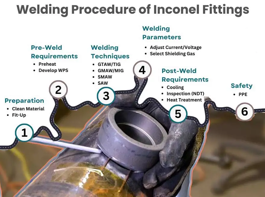
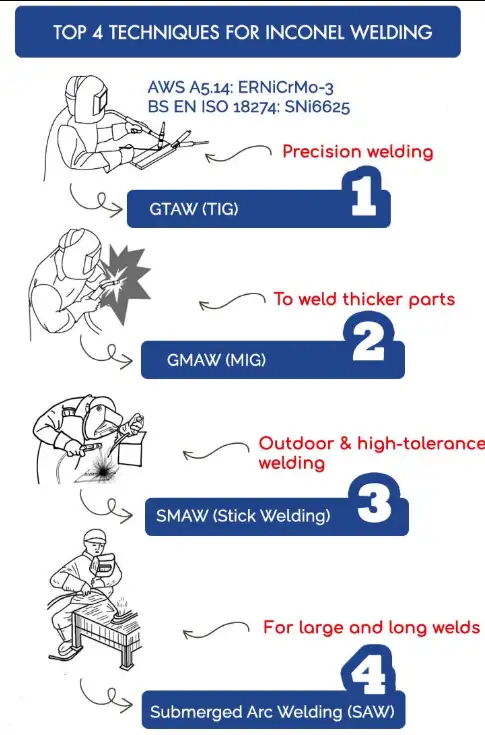
GTAW (TIG): Highest control, preferred for thin sections and root passes; low dilution and excellent cleanliness.
-
GMAW (MIG): Higher deposition rate; suitable for thicker sections and mechanized welds.
-
SMAW (stick): Used for field repairs, lower deposition efficiency, useful when other equipment not available.
-
FCAW/SAW: Used in production, especially for cladding, though SAW is limited to solid solution alloys in some cases.
-
Pulsed GMAW and pulsed GTAW: Useful to control heat input and reduce distortion.
-
Electron beam and laser welding: For precision or minimal HAZ width, used in specialized applications.
Process selection depends on component geometry, required weld quality, mechanic properties, contamination control capability, and access. For critical components, GTAW or mechanized GMAW with controlled parameters is typical.
Filler metal selection: principles and practical pairs
General principles for choosing filler metal:
-
Prefer a filler with chemistry that produces the required corrosion resistance and mechanical behavior in service.
-
For precipitation-hardened base metals, choose fillers that permit desired post-weld heat treatment or that avoid embrittling phases.
-
For dissimilar metal joints, select a filler that minimizes brittle intermetallic formation and controls dilution.
Representative recommended filler choices (industry practice):
| Base metal / application | Common filler(s) | Rationale |
|---|---|---|
| Inconel 625 base metal or dissimilar joints to stainless/steel | ERNiCrMo-3 (UNS N06625) | Matches corrosion resistance and high temperature strength; versatile for dissimilar joins |
| Inconel 718 base metal | ERNiFeCr-2 (AWS classification for 718 filler) or ERNiCrMo-3 in non-strength-critical welds | 718 has a matching filler (ERNiFeCr-2) that can be aged to develop high strength; in many cases alloy 625 filler is used when identical weld strength not required. |
| Inconel 600 and similar Ni-Cr alloys | ERNiCr-3 (Inconel 82) / ERNiCr-3 variants | Good match for Ni-Cr alloys, used widely for welding and dissimilar metal transitions. |
Filler metal specifications and compositions are standardized in AWS A5.14 (nickel and nickel-alloy electrodes and rods) and relevant EN/ISO filler metal standards; following these specs supports consistent weld performance.
Joint design, edge preparation, and fit-up
Key practical points:
-
Keep root faces thin for TIG single-sided full-penetration butt welds; thicker root faces reduce penetration in nickel alloys. Recommended root face thickness for zero-gap TIG butt weld is ≤ 1.5 mm to ensure full penetration. Removable backing strips help control root bead shape and minimize defects.
-
Use clean, oxide-free surfaces; remove oil, paint, and heavy oxides by local mechanical or chemical cleaning immediately before welding. Contamination causes porosity and inclusions.
-
For thick sections, prefer multi-pass welds with controlled interpass temperature to avoid excessive HAZ coarsening and to maintain desired metallurgical microstructures.
Welding parameters and typical ranges
Below are process-specific starting points. Parameters must be qualified by procedure qualification record (PQR) to match code and service requirements.
Table: Typical GTAW/TIG parameter starting points for hand welding (thin to moderate thickness)
| Material thickness (mm) | Electrode diameter (mm) | Current (A) | Travel speed (mm/s) | Shielding gas |
|---|---|---|---|---|
| 0.5–2.0 | 1.0–1.6 | 40–90 | 2–8 | 100% Argon |
| 2.0–6.0 | 1.6–2.4 | 90–160 | 4–10 | 100% Argon |
Table: Typical GMAW parameter starting points (short/controlled spray)
| Wire diameter (mm) | Voltage (V) | Current (A) | Travel speed (mm/s) | Gas |
|---|---|---|---|---|
| 0.8–1.2 | 14–22 | 150–300 | 6–15 | Argon or Ar + small O2/He additions for transfer stability |
Notes:
-
Pulsed modes help to limit heat input on precipitation hardening alloys.
-
Avoid high interpass temperatures on 718; lower interpass supports minimizing HAZ over-aging. Specific interpass limits must be determined by procedure qualification and materials engineering.
Thermal control: preheat, interpass, and post-weld heat treatment (PWHT)
Thermal management is central to performance.
-
Preheat: In most nickel alloys preheat is minimal or zero; high preheat on many nickel alloys increases risk of hot cracking and distortion. For 718 and other precipitation-hardenable grades, preheat is often avoided or kept low.
-
Interpass temperature: Keep interpass temperature low to moderate for precipitation-hardenable alloys; allow the part to cool between passes to maintain favorable microstructure. Excessive interpass temperature can promote undesirable precipitates and reduce toughness.
-
PWHT: Requirements differ by alloy. Alloy 718 typically requires solution anneal and controlled aging to regain design strength after welding of components that must meet full parent-metal strength. Alloy 625 commonly does not require PWHT for corrosion resistance but can be solution treated for specific applications. Follow material supplier recommendations and code requirements for PWHT schedules.
Qualification, documentation, codes, and acceptance criteria
For pressure equipment, rotating hardware, and other critical parts, follow applicable codes and standards:
-
ASME Boiler and Pressure Vessel Code, Section IX, provides qualification rules for welding procedures (WPS) and performance records (PQR). Procedure qualification must demonstrate that the welding procedure produces welds meeting mechanical test requirements. Organizations often write WPS that reference qualified PQRs for a specific range of variables.
-
AWS specifications: A5.14 defines acceptable chemical and mechanical properties for nickel filler metals. Using filler metals to AWS classifications facilitates procedure writing and supply traceability.
-
Material manufacturer technical bulletins provide alloy-specific guidance for welding and heat treatment, and should be referenced in WPS development.
Essential WPS elements for Inconel welding include base material and specification, alloy designation and heat number traceability, filler metal type and classification, welding process and parameters ranges, backing and backing removal, cleaning practice, interpass control, and PWHT requirements.
Common weld defects, root causes, and remediation
Nickel alloys exhibit distinct failure modes; understanding these supports robust procedure development.
Table: Common defects and remediation actions
| Defect | Typical cause | Countermeasure |
|---|---|---|
| Porosity | Contaminants, moisture, inadequate shielding | Clean surfaces, dry filler and flux, ensure correct gas flow and nozzle condition |
| Lack of fusion/penetration | Incorrect joint prep, low heat input, excessive root face | Reduce root face, increase travel angle/heat, use backing or controlled root pass technique |
| Hot cracking/solidification cracking | High segregation in weld metal, high restraint, wrong filler | Use appropriate filler with reduced susceptibility, control restraint, use proper welding sequence |
| HAZ softening or loss of strength (718) | Improper thermal cycle, no PWHT where required | Follow appropriate PWHT schedule or use matching filler permitting heat treatment |
| Strain-age cracking (precipitation-hardenable alloys) | Residual stresses combined with aging precipitates | Minimize stress (post-weld stress relief if allowed), control thermal cycle, avoid high interpass temperatures, consult material supplier |
Dissimilar metal welding and transition joints
Joining to carbon steel or stainless steels is common. Principles:
-
Use a graded transition or appropriate filler to avoid abrupt changes in coefficient of thermal expansion and potential formation of brittle intermetallics.
-
Depositing a nickel-based weld overlay onto steel can provide a corrosion-resisting surface while avoiding full replacement. Matching filler selection and control of dilution are important to maintain desired corrosion performance. ERNiCrMo-3 and ERNiCr-3 series fillers are widely used to join nickel alloys to steels and stainless steels.
Health, safety, and contamination control
Nickel alloy welding produces fumes that may contain nickel and chromium compounds; maintain ventilation and personal protective equipment consistent with local regulations. Prevent contamination:
-
Use dedicated TIG torch consumables for nickel work to avoid cross-contamination from steel; even small iron pick-up changes corrosion resistance.
-
Keep filler wire dry and stored in reels or sealed packaging; dry baking may be required for flux-cored consumables used in critical welding.
Practical step-by-step procedure examples
Below are concise, practical WPS-like outlines for common situations. These are templates; any production use must be backed by PQRs and code review.
Example: Manual GTAW welding of Inconel 625 (thin to medium thickness)
-
Base material: Inconel 625, solution annealed condition.
-
Pre-weld cleaning: Solvent wipe, light grinding to remove heavy oxide, acetone final wipe.
-
Filler: ERNiCrMo-3, diameter 1.6 mm for manual TIG.
-
Backing: Removable copper backing strip if required for root control.
-
Shielding gas: 100% Argon, flow 10–15 L/min. Consider trailing gas cup for post-arc protection.
-
Torch: 2% Thoriated or equivalent tungsten, diameter 1.6 mm, DCEN polarity.
-
Parameters: Current 50–140 A depending on thickness; travel speed to produce proper bead geometry. Use single-pass for thin sections, multi-pass for thick.
-
Interpass: Allow cooling to <150 °C between passes for control of distortion.
-
PWHT: Not required routinely; follow design or supplier requirement.
-
Post-weld cleaning and inspection: Visual, dye-penetrant for surface cracking, radiography or ultrasonic when required.
Example: GTAW/GMAW repair welding on Inconel 718 requiring restoration of strength
-
Pre-weld: Remove aged microstructure near repair zone by local solution treatment if feasible; consult metallurgy expert.
-
Filler: ERNiFeCr-2 (718 filler) to enable post-weld aging response.
-
Heat control: Minimize heat input, use low interpass temperatures.
-
PWHT: After welding, perform solution anneal and controlled aging schedule matching manufacturer specification for full strength recovery. Exact temperatures and hold times must follow Special Metals or supplier data.
Quick-reference tables and appendices
Table: Alloy selection quick-check
| Alloy | Common application | Welding difficulty |
|---|---|---|
| 625 | Chemical processing, marine, gas turbine parts | Easy to moderate |
| 718 | High-strength fasteners, gas turbine discs | Moderate to difficult; requires heat treatment knowledge |
| 600/601 | Heat exchangers, furnace parts | Moderate |
Table: Recommended weld inspection list
-
Visual inspection (all welds)
-
Penetrant testing for surface flaws (thin sections)
-
Radiography for critical butt welds (thick sections)
-
Mechanical tests per code (tensile, bend, impact) during PQR
Frequently asked questions (FAQs)
Q1: Can I weld Inconel 625 without post-weld heat treatment?
A1: In many applications, yes. Alloy 625 is primarily solid solution strengthened; routine PWHT is often not required for corrosion performance. For certain high-temperature design or when joining to specific alloys, follow supplier guidance.
Q2: Must Inconel 718 always receive PWHT after welding?
A2: If the weld and adjacent HAZ must attain full parent-metal strength, then appropriate solution anneal and aging heat treatment steps are required. For non-load-critical minor attachments, designers sometimes accept lower local strength. Always refer to component specification.
Q3: Which filler metal is best for joining 625 to stainless steel?
A3: ERNiCrMo-3 is a commonly used filler for joining Inconel 625 to stainless steels and carbon steels where corrosion resistance is needed in the deposit. Control dilution to maintain required properties.
Q4: Does Inconel warp easily during welding?
A4: Nickel alloys have high strength at elevated temperature which can increase restraint stress; however, careful heat input control, tack weld strategy, and clamping minimize distortion.
Q5: What shielding gas is recommended?
A5: 100% Argon is the default for GTAW and GMAW for most nickel alloys; helium additions are used to increase heat input where necessary, and small oxygen fraction sometimes improves arc stability for mechanized GMAW.
Q6: How to avoid porosity in Inconel welds?
A6: Ensure dry consumables, clean surfaces, correct shielding, and absence of organic contamination. Pre-bake or dry electrodes if stored in humid conditions.
Q7: Can I use 625 filler to weld 718 base material?
A7: 625 filler is sometimes used for 718 welds when full parent-metal strength is not mandatory. For critical high-strength welds, use the matching 718 filler and follow appropriate PWHT.
Q8: Is TIG or MIG better for Inconel?
A8: TIG provides better control for thin or precision welds; MIG offers higher deposition for production. Process choice depends on part geometry and quality targets.
Q9: Are special backing or purge practices required for Inconel pipe welding?
A9: Purging the root side with inert gas to prevent oxidation and to control root bead chemistry is recommended for pipe and tubing welds that demand internal corrosion resistance.
Q10: What codes govern qualification of Inconel welding procedures?
A10: ASME Section IX covers welding procedure qualification for many pressure-vessel and piping applications; AWS standards detail filler metal classifications and testing requirements.
How to build a WPS/PQR for Inconel
-
Specify base material grade and condition, include mill certificates.
-
Select filler metal with AWS or EN classification and provide lot/heat number traceability.
-
Define process, consumable sizes, and welding parameters ranges.
-
Provide cleaning, backing, purge, and interpass temperature control clauses.
-
Define required mechanical testing and acceptance criteria; run PQR(s) to demonstrate the WPS.
-
Specify inspection methods and NDT acceptance limits.
Final recommendations and mistakes to avoid
-
Do not assume all nickel alloys behave identically; consult alloy-specific technical bulletins for required heat treatments.
-
Avoid unnecessary preheat and high interpass temperatures for precipitation-hardening alloys.
-
Use qualified procedures and keep traceability on filler metals and base-metal heats.
-
For dissimilar metal joints, manage dilution and consider cladding or transition layers to protect against galvanic and metallurgical issues.