API Specification 11B sets the industry norm for steel and rod-related products used in reciprocating rod pumps; correct selection of rod grade, size, coupling, and surface treatment — plus proper handling, torque control, and inspection — typically yields the best operating life in a well. For conventional onshore pumping, selecting the correct API grade (C, K, D, HA/HS, or specialty alloys/FRP) based on maximum rod load, corrosion risk, and well depth is the single most important step operators can take to reduce downhole failures and operating cost.
What is API 11B?
API Specification 11B defines dimensional requirements, thread forms, mechanical testing, marking, and product-quality controls for steel sucker rods and related products (pony rods, couplings, polished rods, thread gauges, etc.). The API Monogram program and the standard’s editorial updates are maintained by the American Petroleum Institute; the latest published edition (28th) contains the most current thread, testing and product-identification requirements operators rely on.
Why this matters: conformity to API 11B ensures interchangeability between suppliers, consistent mechanical performance claims, and the availability of calibrated thread gauges and couplings. Non-conforming products significantly increase field risk from improper thread fit, under-spec mechanical strength, and premature failure.
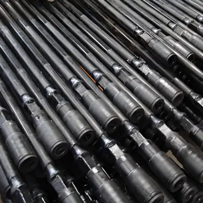
Basic anatomy and function of a sucker-rod string
A sucker-rod string transmits reciprocating motion from the surface prime mover (pumpjack) to the downhole reciprocating pump (plunger and barrel). Primary components:
-
Surface equipment: polished rod, stuffing box, walking beam and horsehead.
-
Rod string: standard sucker rods (25–30 ft / 7–9 m lengths typical) threaded at both ends and joined by couplings.
-
Downhole components: pump barrel, plunger, standing valve and travelling valve.
Rod strings must resist axial tension/compression, bending from lateral well deflection, torque if rotated, and cyclic fatigue from millions of strokes.
Typical retail lengths: 25 ft (7.62 m) and 30 ft (9.14 m). Typical body diameters range from 5/8″ to 1-1/4″ depending on application.
Common sizes and geometric data
| Nominal rod size | Body diameter (inch / mm) | Typical pin size (approx.) | Standard lengths (ft / m) |
|---|---|---|---|
| 5/8" | 0.625″ (15.88 mm) | 1-3/16″ pin | 25 / 30 ft (7.62 / 9.14 m) |
| 3/4" | 0.750″ (19.05 mm) | 1-7/16″ pin | 25 / 30 ft |
| 7/8" | 0.875″ (22.23 mm) | 1-3/8″ pin | 25 / 30 ft |
| 1" | 1.000″ (25.40 mm) | 1-3/4″ pin | 25 / 30 ft |
| 1-1/8" | 1.125″ (28.58 mm) | 1-7/8″ pin | 25 / 30 ft |
| 1-1/4" | 1.250″ (31.75 mm) | 1-7/8″ pin | 25 / 30 ft |
(Note: pins, thread lengths and shoulder dimensions vary by manufacturer and must be checked against API gauge charts during inspection.)
API grades, mechanical properties, and material options
API designation of sucker rods groups products by minimum and maximum tensile properties and often by chemical composition. Below is a condensed practical table — use manufacturer datasheets for precise spec and certification.
| API Grade (typical) | Tensile strength (psi) | Typical composition / notes |
|---|---|---|
| C | 90,000 – 115,000 | Plain carbon steels; lower cost; for shallow, low-load wells. |
| K (nickel-bearing like K) | 90,000 – 115,000 | 1.65–2.00% Ni for corrosion resistance (higher cost). |
| DC / DA variants | 115,000 – 140,000 | Dual-certified or alloy variants for higher loads. |
| D | 115,000 – 140,000 | Higher strength carbon/alloy steels; widely used. |
| HA / HS (high-alloy) | >140,000 (varies) | Special alloys, corrosion resistant options. |
| FRP / Composite | N/A (different metrics) | Glass/epoxy or carbon fiber hybrid, corrosion resistant, low density. |
API 11B provides specific tensile ranges and mechanical test methods for each grade; operators should require material test reports (MTRs) and traceability with each shipment.
Practical note: Higher tensile grades give greater axial capacity but often reduce fatigue life if surface finish, heat treatment and handling are not correct. Proper selection balances static load capacity and fatigue resistance for cyclic loading conditions.
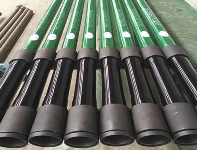
Thread forms, couplings and gauging
API 11B standardizes thread geometry (pin and box), dimensions, and gauging practice. Thread fit must be checked with calibrated plug and ring gauges; torque recommendations and thread lubrication during assembly are essential to avoid galling and to reach the designed engagement. Suppliers commonly provide pin and box thread gages that conform to API specifications.
Common coupling types:
-
Standard couplings (full-round) for same-size rod connections.
-
Reducer couplings to join different diameters when needed.
-
Special couplings with shoulders or stops when running through restricted equipment.
Gauging practice: Check threads for form, pitch, runout and engagement length; reject rods with worn threads or that fail gauge limits.
Surface treatments, coatings and corrosion mitigation
Surface finish and protective treatments dramatically affect fatigue life and corrosion performance. Options:
-
Phosphate or Parkerizing for mild corrosion control on budget installations.
-
Hard chrome plating for polished rod areas; seldom used on sucker rods due to thickness/tolerance concerns.
-
Nitriding or other diffusion hardening improves surface hardness and wear resistance when properly applied.
-
Polymeric coatings or epoxy wraps for partial corrosion protection while maintaining tolerances.
-
FRP/composite rods eliminate many corrosion issues but require different jointing practices.
Choose treatments that do not compromise thread tolerances or heat-treatment induced core toughness. Refer to vendor data because not all coatings are compatible with API thread gauges.
Fatigue, wear and dominant failure mechanisms
Sucker rods operate under high-cycle fatigue; typical failure mechanisms:
-
Fatigue fracture from cyclic axial stress and bending near surface defects or at thread roots.
-
Thread wear and galling from improper torque, poor lubrication, or mismatched threads.
-
Corrosion (general, pitting, H2S/CO2) leading to stress concentration and accelerated fatigue.
-
Erosion from sand and abrasive particles.
-
Buckling and bending in deviated wells causing lateral contact and fretting.
Table — failure mode vs common mitigation:
| Failure mode | Root cause | Practical mitigation |
|---|---|---|
| Fatigue fracture | Repeated stress cycles, surface defects | Specify fatigue-rated grade; shot-peening; surface finish control; remove defects |
| Thread galling | Insufficient lubrication, over-torque | Apply thread compound; use torque wrenches; use correct thread fit |
| Corrosion pitting | Aggressive fluids (H2S/CO2, brine) | Use Ni-bearing or corrosion alloy rods; cathodic protection; inhibitors |
| Erosion | Sand in production | Sand control, filtration, higher hardness surface treatment |
| Fretting wear | Side loading, contact with tubing | Centralizers, proper rod guides, use of wear sleeves |
Notable technical work shows that composites behave differently (rotational bending produces unique fracture modes) and that laboratory fatigue testing in corrosive environments is important when specifying rods for sour or sandy wells.
How to select rod grade and size for a specific well
Selection should account for:
-
Maximum static tensile load at the polished rod (plus safety factor).
-
Dynamic load amplitude during pumping strokes (peak tension and compression).
-
Well depth and rod string weight.
-
Presence of corrosive species (CO2, H2S, chloride).
-
Sand/abrasion risk and likelihood of side loading.
-
Economics: initial rod cost vs expected life; higher grade or coatings often recover costs via longer run life.
Quick decision table (simplified):
| Well scenario | Suggested rod family |
|---|---|
| Shallow, low load, sweet fluids | API C grade or equivalent carbon steel |
| Moderate depth, mild corrosion | K grade (nickel-bearing) |
| High load / deep well | D grade or higher tensile alloy |
| Sour or highly corrosive | HA/HS or corrosion alloy / FRP option |
| High sand or abrasion | Hardened surface treatment; consider increased diameter |
Manufacturer selection charts (from major OEMs) correlate rod load (lbf) vs depth for each grade — consult supplier catalogs for precise limits.
Handling, assembly, torque practice and running procedures
Field practice significantly affects rod life. Key recommendations:
-
Use torque-wrenches and follow supplier torque tables during coupling make-up; avoid hammering threads.
-
Apply approved thread compound for both lubrication and corrosion protection; ensure compound does not alter gauge fit.
-
Do not over-rotate or rotate continuously unless the rod is specified for rotation; rotating conventional steel rods increases torsional stresses and reduces fatigue life. Some screw-type pumps require rod rotation — use rods and couplings rated for torque.
-
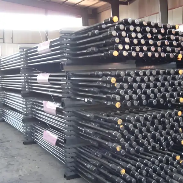
Implement careful storage: keep rods off ground, covered from moisture; inspect threads before running.
-
Mark and track rod runs and re-use only per supplier recommendations; maintain run-cards documenting replacements and failures.
Inspection, nondestructive tests and replacement criteria
Routine inspection should include:
-
Thread gauging (plug and ring) before running.
-
Visual inspection for corrosion pitting, thread damage, nicks, and surface defects.
-
Ultrasonic or magnetic particle testing for critical rods when fatigue damage is suspected.
-
Hardness verification and tensile testing on sampled lots for quality assurance.
Replace rods with threads worn beyond gauge acceptance, with cracks detected by NDT, or with significant pitting/section loss that reduces cross-sectional area or fatigue strength.
Emerging alternatives: FRP and hybrid composite rods
FRP rods (glass or carbon fiber with epoxy matrix) provide advantages:
-
Lower weight (reduces static load and may increase allowable pump depth).
-
Resistance to corrosion from formation fluids.
-
Electrical insulation (helps on stray current or galvanic concerns).
Limitations:
-
Different jointing and coupling systems; special training required.
-
Different failure modes (matrix cracking, delamination) and different inspection criteria.
-
Cost per foot often higher, but life-cycle economics can favor FRP in corrosive wells. Technical catalogs and lifecycle case studies should be consulted when considering composites.
Economic considerations: life-cycle cost vs initial outlay
Evaluate:
-
Mean time between failures (MTBF) for candidate rod types in similar wells.
-
Downtime cost per failure (lost production + workover).
-
Unit cost per foot and cost of coatings or special handling.
-
Re-use policies and refurbishment costs.
Often a higher-grade rod or an FRP string reduces total cost per year by extending run life and lowering remedial workover frequency.
Quick procurement checklist
-
API 11B compliance statement and edition cited.
-
Mill test reports (MTRs) for chemical and mechanical properties.
-
Thread gauge certifications and calibration records.
-
Traceability (heat number, batch ID).
-
Recommended torque charts and assembly instructions.
-
Corrosion/coating documentation if applicable.
-
Warranty or replacement policy for premature failures.
Practical tables and comparison snapshots
Table A — Typical mechanical property summary
| Grade | Min tensile (psi) | Max tensile (psi) | Typical hardness (HRC/BHN) |
|---|---|---|---|
| C | 90,000 | 115,000 | ~180–230 HB |
| K | 90,000 | 115,000 | similar to C but with Ni content |
| D | 115,000 | 140,000 | 200–260 HB |
| HA/HS | >140,000 | vendor specified | vendor specified (heat treated) |
(Consult API 11B and vendor data for legally binding values.)
Table B — Rod length and recommended use
| Length | Use case |
|---|---|
| 25 ft | Many onshore installations; easier transport and handling |
| 30 ft | Deeper wells; fewer couplings but heavier single piece handling |
Failure case studies
-
Case — thread fatigue at pin shoulder: Often caused by insufficient engagement length and minor machining grooves near the thread root. Corrective actions: improved machining tolerances, root radius control, and routine NDT of suspect lots.
-
Case — corrosion-assisted fatigue in sour well: Operator switched to nickel-bearing or specialty alloy rods and applied aggressive corrosion inhibitors; run life improved significantly though material cost rose.
Field best practices checklist
-
Keep rod racks dry and off soil.
-
Record every rod run number and condition.
-
Use calibrated torque tools and recommended compounds.
-
Inspect threads before make-up, and after pulling, mark suspect rods for NDT.
-
Match rod selection to both static loads and cyclic stresses; simulate cycles where possible.
Ten practical specifications to include in a purchase order
-
Quote API 11B edition number and require supplier conformance.
-
Specify grade and tensile range by API designation.
-
Request MTRs for each heat lot with chemical analysis and tensile/hardness tests.
-
State required thread gage certificates.
-
Declare coating/surface treatment with tolerances.
-
Mandate packaging to prevent thread damage.
-
Include acceptance sampling plan for NDT.
-
Define warranty terms for premature fatigue failure.
-
Specify thread compound compatibility and torque values.
-
Require traceability marking on each rod (heat number).
Frequently Asked Questions
Q1: What is API 11B and why obligate it in purchase orders?
A1: API 11B is the accepted specification for sucker rods and rod-related products; including the edition in a PO ensures suppliers must meet standardized thread forms, testing and marking practices. This reduces interchange problems and protects field operations.
Q2: How do I choose between steel and FRP rods?
A2: Evaluate corrosion levels, desired reduction in rod weight, and total cost of ownership. Steel is economical in many sweet wells; FRP may be superior in highly corrosive or deep lift applications where reduced weight and corrosion resistance deliver net savings.
Q3: Can I rotate API steel rods?
A3: Only if the rod system and couplings are rated for torque and rotation; rotation increases torsional and bending stresses—standard practice is to avoid rotation unless required by pump design and rod material permits it.
Q4: What are the most frequent causes of thread failure?
A4: Improper make-up torque, contaminated threads, worn or mismatched gauges, and poor thread form control at manufacturing. Regular gauging and correct torque application mitigate these failures.
Q5: How often should rods be inspected?
A5: Inspect each rod visually and with thread gauges before running. For suspect strings or after unusual events, apply NDT such as magnetic particle or ultrasonic testing on sampled rods.
Q6: Are there standard torque charts?
A6: Yes, most OEMs publish torque charts per rod size and coupling; these should be followed and tools calibrated. Refer to supplier documentation for exact values.
Q7: What grades resist sour corrosion?
A7: Nickel-bearing grades and high-alloy rods, or FRP rods, resist sour and chlorinated environments better than plain carbon steel; always match material to chemistry and pressure/temperature conditions.
Q8: How do I reduce rod fatigue in deviated wells?
A8: Use centralizers, wear sleeves, increase rod diameter, reduce side loading by better wellbore conditioning, and specify fatigue-tolerant grade/finish.
Q9: Can I refurbish and reuse old rods?
A9: Some rods can be refurbished by re-threading and inspecting provided the remaining cross-section and heat treatment meet design limits; always consult the supplier and perform NDT before reuse.
Q10: What documentation should arrive with each rod shipment?
A10: MTRs, thread gage certification, heat numbers, marking verification, and handling/assembly instructions. These documents support product traceability and warranty claims.
Closing recommendations
-
Require API 11B conformity in the PO and confirm edition.
-
Match grade to dynamic load and corrosion environment; when in doubt, consult OEM selection charts.
-
Implement disciplined gauging, torque control and inspection protocols to prevent most common field failures.