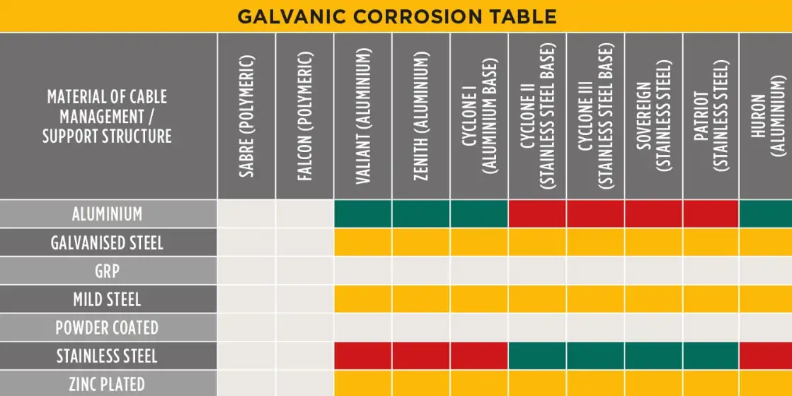
Galvanic corrosion will cause aluminum to corrode preferentially when it is electrically connected to stainless steel in a conductive environment; this risk grows when the electrolyte contains chlorides, when the aluminum area is small relative to the stainless steel area, or when crevices and poor coatings exist. Proper material selection, electrical isolation, protective coatings, careful joint design, and adherence to recognized testing standards can reduce likelihood and service costs dramatically.
Fundamental electrochemistry behind galvanic corrosion
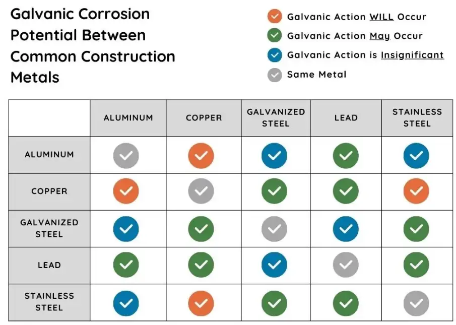
Galvanic corrosion occurs when two dissimilar metals form an electrical circuit through an electrolyte. In that circuit one metal becomes the anode and loses metal ions, while the other becomes the cathode and remains protected. The direction of attack depends on the relative electrochemical potential of each metal in the environment in question. When aluminum contacts stainless steel, aluminum normally sits at a more negative potential; therefore it becomes the anode and corrodes. The corrosion current and resulting mass loss depend on potential difference, conductivity of the electrolyte, and the exposed surface area ratio of cathode to anode.
Where stainless steel + aluminum pairings appear in industry
Common pairings include:
-
Marine hardware: aluminum hull fittings with stainless steel rigging or fasteners.
-
Transport: vehicle body panels (aluminum) and stainless brackets or bolts.
-
Architectural façades: aluminum curtain wall components joined to stainless element frames.
-
Electronics enclosures: aluminum housings with stainless connectors.
-
Offshore platforms and renewable-energy supports.
In each instance wetting with seawater, condensation, or de-icing salts raises risk. Practical guidance must therefore address environment, duty cycle, and galvanic potential.
Environmental factors that change the risk profile
Key environmental drivers:
-
Electrolyte chemistry: chloride-rich solutions (seawater, de-icing salt) raise conductivity and drive higher corrosion currents.
-
Temperature: elevated temperature often increases corrosion reaction rates and may change relative potentials.
-
Aeration and flow: oxygen concentration and flow rate influence formation and breakdown of protective oxide films on aluminum; low-oxygen crevices can produce strong localized attack.
-
pH and pollutants: acidic or alkaline conditions shift potentials and change which alloy phases are stable.
-
Time of wetness: longer periods with electrolyte present produce more cumulative damage.
When evaluating a design, quantify these parameters rather than rely on heuristics.
The galvanic series and the area effect
The galvanic series ranks metals by their electrochemical potential in a given environment (usually seawater for common reference). Aluminum alloys are significantly more active (less noble) than typical stainless steels; this difference produces a driving voltage for galvanic current. The area ratio effect multiplies damage: a small aluminum anode coupled to a large stainless steel cathode will suffer much higher current density and faster corrosion than a large aluminum area paired with a small stainless area. Engineers must evaluate both potential difference and exposed area ratio when predicting life.
Practical failure modes and real-world examples
Common manifestations:
-
Uniform thinning of aluminum near contact points with stainless fasteners.
-
Crevice corrosion at joints where trapped moisture breaks down oxide layers.
-
Pitting and exfoliation on high-stress panels in marine environments.
-
Fastener loosening due to corrosion product build-up or loss of cross-section.
Case studies in maritime maintenance logs and published corrosion proceedings show aluminum hull fittings failing within months when improperly coupled to stainless fittings in regular seawater splash zones.
Standards, test methods, and how to interpret results
A robust corrosion-control program uses recognized standards to screen materials and coatings, to simulate service conditions, and to quantify susceptibility.
Key standards and practices:
-
ASTM G71 — galvanic corrosion testing under controlled laboratory conditions; provides protocols to measure galvanic current and potential between coupled metals.
-
ASTM G1, G31, G46 — specimen preparation, immersion testing, and evaluation of pitting and crevice corrosion.
-
ISO 8057 (2024) — electrochemical procedures for determining galvanic corrosion rates in assemblies with protective coatings; relevant for coated aluminum/stainless combinations.
-
Galvanic series development — ASTM and industry bodies recommend deriving a galvanic series under the specific environmental conditions of the application rather than relying solely on generic charts.
Interpretation rules:
-
Run tests in representative electrolytes (salt concentration, temperature, flow).
-
Report both potential difference and galvanic current density.
-
Include area-ratio scenarios that reflect likely assemblies.
-
Consider long-term exposure tests rather than only accelerated screening.
Design principles to avoid galvanic attack
Good design reduces electrical contact, reduces electrolyte access, and avoids small-anode/large-cathode pairings.
Practical rules:
-
Keep like metals together when possible.
-
If mixed metals must be used, place the more noble metal where exposure to electrolyte is limited, or increase the anodic area to reduce current density.
-
Electrically isolate interfaces using nonconductive barriers (gaskets, nylon washers, polymer sleeves) when load transfer allows.
-
Avoid crevices that trap moisture; provide drainage and ventilation.
-
Use coatings on the anodic aluminum surface that provide durable barrier protection; ensure coating continuity under fasteners.
-
Use fasteners whose metallurgy and surface finish have proven compatibility with the specific aluminum alloy in the targeted environment.
These principles are consistent with published industry recommendations on minimizing dissimilar-metal contact in marine and architectural practice.
Mitigation techniques
This section lists mitigation options, benefits, limits, and implementation notes.
Surface treatments and coatings
-
Conversion coatings (e.g., chromate, non-chromate alternatives): improve paint adhesion and provide some sacrificial protection to aluminum. Ensure environmental compliance with chromate restrictions.
-
Organic primers and topcoats: high-performance epoxy or polyurethane systems reduce moisture ingress. Coating continuity around fasteners is crucial.
-
Anodizing (for aluminum): thick anodic films increase barrier properties but may require sealing; anodized aluminum that is mechanically abraded near stainless contact points can still corrode.
Coating selection should be validated by ASTM/ISO immersion and cyclic corrosion tests.
Electrical insulation
-
Nylon or PTFE washers, polymer sleeves, resin-filled joints: simple, low-cost isolation often solves the issue for static connections.
-
Design caution: insulation can trap moisture if not detailed properly; prefer designs that allow drainage.
Fastener choices
-
Use compatible fastener/alloy pairings: some stainless grades (e.g., duplex or high-moly stainless) may perform differently; in many cases using aluminum alloy fasteners or coated stainless fasteners reduces risk.
-
Use sacrificial zinc or aluminum washers/anodes in marine fittings where isolation is impractical.
Cathodic protection and sacrificial anodes
-
Sacrificial anodes (zinc, aluminum, magnesium): commonly used on hulls and offshore structures to protect large assemblies. Effective when properly sized and maintained.
-
Impressed-current systems: suitable for large buried or submerged structures, but require monitoring and maintenance.
Design hygiene and maintenance
-
Avoid trapping salts on horizontal surfaces.
-
Schedule inspections focusing on fastener fields and joints.
-
Touch-up coatings promptly after damage.
For all mitigation options, quantify expected lifetime gains with lab or field trials rather than rely on rules of thumb.
Inspection, maintenance, repair, and lifecycle planning
A lifecycle plan should include:
-
Baseline condition recording at installation.
-
Scheduled inspections focusing on high-risk junctions and record corrosion rates if possible.
-
Non-destructive evaluation for fasteners and thin panels (ultrasonic thickness, eddy current).
-
A repair protocol: remove corrosion products, verify substrate integrity, select compatible repair materials, and recoat using validated systems.
-
Replacement criteria: when cross-sectional area loss reduces structural capacity below safety margins.
Document findings and update design standards for future projects. Historical data often shows that early visual signs near stainless/aluminum joints predict later rapid degradation.
Comparative tables
Table 1 — Typical galvanic potential ranges in seawater (selected)
| Material | Typical potential vs Ag/AgCl (V) | Typical behavior when coupled with stainless steel |
|---|---|---|
| Aluminum alloys | −1.1 to −0.75 | Strongly anodic; will corrode when coupled to stainless in electrolyte. |
| Stainless steels (passive) | −0.50 to −0.30 | Cathodic relative to aluminum in seawater; remains protected. |
| Copper alloys | −0.30 to −0.10 | Near stainless behavior; less severe coupling with SS but can still cause aluminum attack. |
| Zinc (sacrificial) | −1.0 to −0.9 | Anodic; used intentionally as sacrificial anode. |
Table 2 — Mitigation method matrix
| Method | Ease of implementation | Typical cost | Effectiveness (marine environments) | Notes |
|---|---|---|---|---|
| Electrical isolation (washers/sleeves) | High | Low | High if detailed correctly | Watch for trapped moisture |
| Coating system on aluminum | Medium | Medium | High | Must be continuous; validate with cyclic tests. |
| Anodizing + sealing | Medium | Medium | Medium–High | Good for some alloys; mechanical damage reduces benefit |
| Sacrificial anode system | Low | Low–Medium | High (for submerged structures) | Requires maintenance |
| Use of aluminum or plated fasteners | High | Low–Medium | Medium | Consider mechanical properties and galvanic trade-offs |
Table 3 — Fastener selection checklist
| Consideration | Recommendation |
|---|---|
| Use environment | For splash or seawater, avoid bare stainless fasteners on bare aluminum unless isolated. |
| Coating under head | Apply non-conductive coating or washer to separate metals. |
| Thread locking | Prefer non-conductive mechanical locking rather than conductive adhesives that may bridge metals. |
| Torqueing | Avoid over-torque that abrades coatings and breaks anodic film |
Frequently asked questions
Q1: Can stainless steel and aluminum be used together in outdoor applications?
Yes, they can be used together when specified isolation, coatings, or sacrificial protection are applied and when the assembly is designed to avoid small-aluminum/large-stainless area ratios and trapped moisture.
Q2: Which stainless grade is safest to pair with aluminum?
No single stainless grade is guaranteed safe; selection depends on environment and alloy. The key is control of electrical contact and electrolyte access rather than relying solely on stainless chemistry. Test the actual couples in simulated service conditions.
Q3: Do plated stainless fasteners solve the problem?
Plating can help if it provides a durable, insulating barrier; however, thin or damaged plating may fail and create concentrated corrosion sites. Use thick, proven coatings and verify with cyclic testing.
Q4: Will painting both metals stop galvanic corrosion?
A continuous, intact coating on both metals reduces risk greatly. Punctures, damaged edges, or incomplete coverage around fasteners reduce protection and can concentrate attack.
Q5: How important is the area ratio?
Very important. A small aluminum anode exposed to a large stainless cathode can experience high current density and rapid loss. Maintain conservative area ratios and test designs where high cathode/anode exposure is unavoidable.
Q6: Is anodized aluminum safe with stainless steel?
Anodizing improves barrier resistance. However, mechanical damage or abraded areas near stainless contact points still permit galvanic action. Use sealing and isolation for critical joints.
Q7: Are polymer washers a long-term solution?
They are effective when exposed to predictable loads and weathering is limited. Verify UV, creep, and chemical resistance of the polymer in the intended environment. Design for drainage.
Q8: Should I use sacrificial anodes on architectural aluminum?
Sacrificial anodes are typically used in marine/submerged applications rather than exposed architectural elements. For buildings, coatings and isolation are usually preferred.
Q9: How should I test my assembly?
Follow ASTM test methods for galvanic coupling and immersion testing, run cyclic salt-spray and wet/dry cycles matched to expected service conditions, and measure galvanic currents and mass loss.
Q10: Who should I consult for complex systems?
Corrosion engineers, coating specialists, and organizations experienced in marine corrosion studies (independent labs, classification societies) should validate designs using standards-based testing.
Implementation checklist for engineers
-
Map all dissimilar-metal contact points.
-
Determine environmental exposure (electrolyte chemistry, time of wetness, temperature).
-
Calculate cathode/anode area ratios for the worst-case assembled state.
-
Select coatings and isolation materials that survive local service conditions.
-
Run ASTM/ISO tests that model service electrolyte and thermal cycles.
-
Create inspection intervals based on predicted corrosion rates.
-
Record field data, then refine material choices for next design iteration.
Closing summary
Aluminum will usually be the sacrificial element when it touches stainless steel in conductive conditions. That basic fact must shape materials selection, joint detailing, and maintenance planning. Engineers should not rely on off-the-shelf charts alone; instead they should select test conditions that replicate real exposure, design for isolation or coatings, and schedule inspection programs appropriate for the environment. When implemented correctly, these measures transform an inherently risky pairing into a reliable, long-lived assembly.
Authoritative references
- Stainless Steel in Waters: Galvanic Corrosion and Its Prevention — Nickel Institute (technical paper)
- ASTM Corrosion Tests and Standards — ASTM International
- Galvanic Series in Seawater as a Function of Temperature — NACE/AMPP Proceedings
- ISO 8057 (2024) — Determination of galvanic corrosion rate (scope & procedures) — ISO