The correct joint choice depends on part geometry, load path, access, material thickness, required weld penetration, and production volume. For general structural work, fillet welds in T, lap, corner joints and groove butt welds are the most frequently used. Precision pressure-containing assemblies typically use carefully prepared groove butt joints with full-penetration welds. Proper edge preparation, correct welding process selection, and compliance with welding symbols and quality standards are critical to produce reliable welds.
Definitions and classification
A welded joint is the local region where two or more parts are joined by a weld metal deposit. Classification may rest on geometry (butt, lap, corner, edge, T), penetration (partial, full), and weld type (groove, fillet, plug, spot, seam, projection). Designers must think in terms of load transfer, fatigue exposure, corrosion exposure, and inspection accessibility when picking a joint.
The five classical joint families and their variations
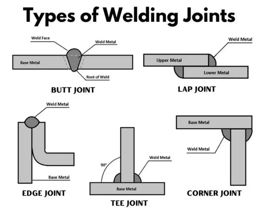
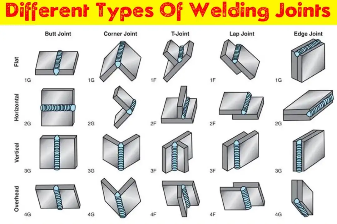
Industry practice groups welded joints into five primary families: butt, T (also called tee), lap, corner, and edge. Each family admits several geometric and welding-process variants (for example, a butt family includes square-groove, single-V, double-V, single-J, bevel, and U groove). These five families are the backbone of general welding practice.
Short definitions:
-
Butt joint: two members in the same plane, meeting at their edges. Common for pipes and plates where through-thickness strength and pressure containment matter.
-
T (tee) joint: one member perpendicular to the other, forming a T-shape. Often welded with fillet welds.
-
Lap joint: one member overlaps another. Common in sheet-work and thin-gauge fabrication.
-
Corner joint: edges meet to form an L-shaped corner—often used in box structures and frames.
-
Edge joint: edges lie parallel and are joined at the common edge; useful for joining sheet edges together for seam welds and for reinforcement.
Extended joint types and specialty joints
Beyond the five families there are specialty joints used for fabrication convenience or to satisfy specific functional needs:
-
Plug and slot welds: used to join overlapping sheets where access precludes fillet welds or where a spot weld is insufficient.
-
Seam welds (resistance seam): continuous resistance weld used for tubes and tanks.
-
Spot welds (resistance spot): for sheet metal assemblies in volume production.
-
Projection and stud welds: used in fast-assembly parts.
-
Flash and upset welding: for thermomechanical joining of bars and rings.
-
Edge/butt combinations: butt welds with partial penetration plus intermittent fillet for distortion control.
Groove and fillet weld types — geometry and nomenclature
Groove welds fill a prepared groove between parts to achieve penetration; fillet welds join surfaces at roughly right angles producing a triangular cross-section. Common groove shapes:
-
Square-groove (no preparation)
-
Single bevel (one part beveled)
-
Single V (both parts beveled to make a V)
-
Double V (bevel on both faces for welding from both sides)
-
J-groove (one side contoured with a J radius)
-
U-groove (curved bottoms on both sides)
-
Flare V/Flare bevel (for joining round to flat)
Groove weld geometry uses terms: groove angle (α), root opening (gap), root face (land), and weld face. Proper control of these dimensions influences penetration, welding time, and distortion.
Joint design parameters — recommended ranges and engineering tradeoffs
Design choices balance strength, fatigue, access, and fabrication cost. Key parameters:
-
Groove angle: larger angle improves access and fusion but increases weld volume and filler metal. Typical single-V angles range from 45° to 60° (included angle), but thin materials may use smaller angles.
-
Root gap (root opening): for full-penetration butt welds, gaps from 0.5 mm to several millimetres are used depending on thickness and welding process.
-
Root face (land): often 0–2 mm depending on procedure; some specifications require a small land to control penetration.
-
Bevel type: J and U grooves reduce filler metal needs for thick sections but require machining.
-
Intermittent weld leg length and pitch for fillet welds: used to reduce heat input and distortion in long joints.
Table 1 (joint design quick parameters) below provides practical ranges recommended in common practice (note: project-specific codes prevail for pressure vessels and critical structures).
| Joint / Element | Typical Range or Note |
|---|---|
| Single V groove angle (included) | 60°–90° (thin sections at lower end) |
| Double V groove angle (each side) | 30°–60° |
| Root gap (thin sheets) | 0–1.5 mm |
| Root gap (thick plate) | 1–6 mm (process dependent) |
| Root face / land | 0–2 mm |
| Fillet weld leg (structural) | 4–10 mm common |
| Minimum weld throat (for coded pressure) | See governing code (ASME/ISO) |
Of Welding Joints
Selection matrix — which joint for which application
Choose a joint by mapping service requirements (static load vs fatigue, corrosive environment, cyclic thermal loading) and production constraints:
| Application | Typical Joint | Why |
|---|---|---|
| Pressure pipe / vessel | Full-penetration butt groove (single/double V, J, U) | Need leak-tight strength and fatigue resistance |
| General structural frame | T-joint or lap with fillet welds | Fast production, adequate static strength |
| Thin sheet panels | Lap or spot/seam welds | Efficient for mass production |
| Sheet-to-tube or flange | Flare-bevel to V junctions | Match geometry and ensure fusion |
| Corrosion-exposed joints | Full weld cap and backing techniques | Avoid crevices and corrosion traps |
Process compatibility and common pairings
Different welding processes suit different joints:
| Joint Type | Preferred processes |
|---|---|
| Butt full-penetration (thin plate) | GTAW (TIG), GMAW (MIG), SMAW |
| Butt full-penetration (thick plate) | SAW (Submerged Arc), FCAW, mechanized GMAW |
| Fillet welds (T, lap) | GMAW, FCAW, SMAW |
| Spot/seam (sheets) | Resistance spot / seam welding |
| Plug/slot (overlap) | GMAW, SMAW, robotic GMAW for production |
Choice depends on required metallurgy, base metal, joint access, heat input limits, and productivity. SAW provides high deposition rates on groove welds for long seams. GTAW gives best control for small diameter or thin materials.
Preparation, fit-up, and tolerances
Fit-up controls final weld quality. Controlled root gap and alignment reduce incomplete penetration and minimize rework. Typical fabrication best practices include:
-
Pre-machined bevels for thick sections (J, U grooves) to control weld volume.
-
Backing strips or ceramic backing to support root and improve weld quality for single-side welding.
-
Tack weld pattern to hold alignment, minimize distortion, and reduce gap changes during welding.
-
Use of clamps and fixtures to maintain preheat zones in cold environments.
For critical fabrications, reference ISO 9692 for recommended joint preparation dimensions and permitted alternatives.
Welding symbols, drawing notation, and standards
Clear drawing communication reduces errors. Two primary schools of symbolic practice are AWS and ISO. AWS publishes A2.4 (standard symbols for welding, brazing, and nondestructive examination); ISO issues ISO 2553 (symbolic representation on drawings for welded joints). Use the correct standard consistently for procurement and quality control.
A few recommended practices:
-
Place the complete welding symbol with dimensions on one detail and use “typical” to reduce drawing clutter.
-
Always include groove dimensioning: root opening, groove angle, weld size, and required weld process if necessary.
-
Specify weld quality and acceptance criteria referencing standards (for example, ISO 5817 or project code).
Common defects by joint type and mitigation
Defect patterns often correlate with joint geometry and process:
-
Incomplete fusion / lack of penetration (common in butt groove joints): caused by low heat input, incorrect angle, or contaminated surfaces. Mitigate by increasing heat, adjusting travel angle, or improving fit-up.
-
Porosity (common in fillet and groove welds): contamination, entrapped moisture, or shielding gas issues. Use dry consumables and proper gas flow.
-
Undercut (fillet and groove faces): too high welding current or improper electrode/torch manipulation. Reduce current or change technique.
-
Excessive distortion (long butt joints): high heat input and unbalanced welding sequence. Use back-gouging and balanced multi-pass welding (double V) to reduce heat input on one side.
-
Cracks (hot or cold): poor joint design, high restraint, or unsuitable filler metallurgy. Select compatible consumables and preheat/postheat according to code.
Nondestructive testing (NDT) and acceptance
NDT selection depends on the joint criticality:
-
Visual (VT): baseline for all welds.
-
Penetrant Testing (PT): surface-breaking defects on non-porous metals.
-
Magnetic Particle (MT): for ferromagnetic materials to find surface and near-surface defects.
-
Radiography (RT): volumetric detection of internal defects for butt welds.
-
Ultrasonic Testing (UT): volumetric detection, improved sensitivity for thicker sections.
Standards like ISO 5817 and project-specific codes specify acceptance levels (B, C, D) and allowable imperfection sizes. For pressure or fatigue-critical joints, RT or UT is common.
Productivity and cost tradeoffs
Designers must trade fabrication cost against service requirements:
-
Fillet welds are low-cost and fast; often sufficient for static loads.
-
Full-penetration groove welds cost more but yield greater strength and fatigue life.
-
J and U grooves reduce filler volume for thick plates but require machining, which adds cost.
-
Mechanized processes (SAW, robotic GMAW) provide lower unit cost for long runs but require capital investment.
Tables — compact references
Table A — Common joint types, typical weld, common processes, pros/cons
| Joint | Typical Weld | Typical Processes | Key Pros | Key Cons |
|---|---|---|---|---|
| Butt (square) | Square groove / fillet for lap | GTAW, GMAW, SMAW | Simple prep, low machining | Limited on thick sections without prep |
| Butt (single V) | V groove full- or partial-penetration | SAW, GMAW | Good access on one side | More filler metal |
| Butt (double V) | Double V groove | GMAW, SAW | Lower weld volume per side, less distortion | Requires welding both sides |
| T-joint | Fillet | GMAW, SMAW, FCAW | Fast | Stress concentrations at toe; fatigue concern |
| Lap joint | Fillet/plug | Resistance spot/seam, GMAW | Good for thin sheet | Crevice corrosion risk |
| Corner joint | Fillet/groove | GMAW, SMAW | Good for boxes | Gap/fit-up critical |
| Edge joint | Fillet/seam | Resistance seam | Efficient for seams | Limited strength |
Table B — Groove types and typical engineering notes
| Groove | Typical use | Note |
|---|---|---|
| Square | Thin plate butt | Minimal prep |
| Single bevel | Plate-to-plate where access limited | Saves machining on one side |
| Single V | Common for general butt welds | Balance between prep cost and filler metal |
| Double V | Thick plates | Weld both sides to control distortion |
| J, U | Thick sections | Lower filler metal needs; higher prep cost |
| Flare bevel | Tube-to-plate | Matches tube curvature |
Table C — Joint vs inspection method
| Joint | Recommended NDT |
|---|---|
| Full-penetration butt | RT / UT plus VT |
| Fillet weld (structural) | VT ± MT/PT depending on material |
| Resistance spot/seam | VT and mechanical tests; sample destructive testing for qualification |
| Plug/slot | VT, PT/MT as needed |
Practical fabrication checklist
-
Review drawing symbols and confirm which standard applies (AWS A2.4 or ISO 2553).
-
Confirm material and thickness; consult ISO 9692 for joint prep when in doubt.
-
Verify filler metal and procedure qualifications are in the WPS (welding procedure specification) and that welding operators hold relevant qualifications (ASME Section IX or ISO 9606 where required).
-
Check fit-up tolerances, tack pattern, and backing or root support.
-
Choose sequence and interpass temperature limits to minimize distortion and meet metallurgical requirements.
-
Specify inspection plan referencing acceptance criteria (ISO 5817 or project code).
-
ISO 9692 series gives recommended joint preparation geometries by process and material; helpful for deciding groove types and machining requirements.
-
AWS A2.4 (and AWS documentation on welding practice) provides the commonly used symbol set and conventions for many North American projects.
-
ISO 2553 standardizes symbolic representation on drawings and can be preferable for internationally executed projects.
-
ASME BPVC Section IX covers qualification of welding procedures and welders for pressure-boundary components and is required for boiler and pressure-vessel work in many jurisdictions.
-
ISO 5817 defines quality levels for imperfections in fusion-welded joints; use it to set acceptance criteria.
FAQs
1. Which weld joint is strongest?
Strength depends on load direction. For axial through-thickness loading, a properly executed full-penetration butt weld has the best strength-to-section continuity. For shear loads, continuous fillet welds with sufficient throat size can be effective.
2. What joint is best for thin sheet metal?
Resistance spot welding or seam welding is often the most economical for high-volume thin sheet production. For manual welding, lap fillet joints are common.
3. When should I use a J or U groove instead of a V?
Use J or U on thick plate where filler metal volume matters and when budget allows for machining. These grooves lower the required filler and reduce weld metal shrinkage.
4. How large should the root gap be?
Root gap depends on thickness, process, and code. For thin sheets it may be near zero. For thicker plates, 1–6 mm is common. Always follow the WPS and referenced standards.
5. How do welding symbols differ between AWS and ISO?
They share many elements, but conventions for arrow side/other side and some symbol shapes differ. Use the single chosen system consistently on a set of drawings.
6. How to reduce distortion in long butt welds?
Use balanced welding (double-sided welding when possible), back-gouging and welding from alternate ends, stitch welding, and preheat/postheat control.
7. What inspection method suits thick butt welds?
Radiographic testing (RT) or ultrasonic testing (UT) provide volumetric inspection; UT is often preferred for thicker sections and where radiation safety is a concern.
8. Are fillet welds acceptable for pressure-containing joints?
Not usually for high-pressure boundary joints. Pressure vessels and piping generally require full-penetration groove welds with qualified procedures.
9. How important is edge preparation?
Critical. Poor preparation leads to lack of fusion, incomplete penetration, and increased defect rates. ISO 9692 provides recommended preparations.
10. Which standards should I reference on international projects?
Prefer ISO 2553 for symbols, ISO 9692 for joint prep, ISO 5817 for acceptance criteria, and the relevant code (e.g., ASME BPVC) for pressure-containing work.
Short case study (practical scenario)
Scenario: Fabrication of a 20 mm thick carbon-steel flange weld to a pipe that will operate under cyclic pressure.
Recommendation: Use a single- or double-V full-penetration butt weld depending on access. If welding from one side only, prepare a single-V with a moderate root gap and ceramic backing; execute a qualified WPS with multiple passes, control interpass temperature, and perform UT after welding per project NDT plan. Consider post-weld heat treatment if required by metallurgy and service. Reference ISO 9692 for groove geometry and ASME Section IX for procedure/ welder qualification.
Closing practical tips
-
Standardize joint preparation templates to reduce machining errors.
-
Keep consumables dry and storage controlled to avoid porosity.
-
Use fillet-gauge and weld gauges for rapid on-floor checks.
-
Include welding symbols with dimensions on the drawing; avoid ambiguous shorthand.
Authoritative references
- ISO 2553:2019 — Welding and allied processes — Symbolic representation on drawings — Welded joints
- ISO 9692 series — Welding and allied processes — Recommended types of joint preparation for various welding processes
- AWS A2.4:2020 — Standard Symbols for Welding, Brazing, and Nondestructive Examination
- ASME Boiler and Pressure Vessel Code (BPVC) — Section IX: Welding, Brazing, and Fusing Qualifications
- ISO 5817:2023 — Welding — Fusion-welded joints — Quality levels for imperfections